32 Rev. 03/2019
5.1 Unpacking
Unpack the equipment, taking care not to damage it. Always place the device safely and
protected from falling over or falling down. Ensure that the operating manual is always stored
with the ignition controller and is easily accessible. Check the contents for completeness and
verify that the device type meets your application requirements.
Scope of Supply
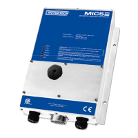
The scope of supply of the MIC5 ignition controller consists of the following components:
– Ignition controller of the MIC5 series
– Installation set incl. four vibration dampers
– Ground strap
– Three multiple sealing inserts and five sealing plugs for PG screw joints
– Storage device (USB flash drive or CD-ROM) with software for configuring the ignition
controller
– USB interface cable for connecting the ignition controller to a PC/laptop
– Operating manual
5.2 Installation of the Ignition Controller
The installation of the MIC5 ignition controller is implemented on a fixed bracket e. g. on a wall
near the engine. Use the included rubber vibration dampers and the ground strap. The
installation location of the controller must be selected so that the distance to the pickups
installed on the engine ensures a reliable signal transmission to the ignition controller, and so
that there is adequate space for maintenance and repair work. The mechanical specifications
must always be complied with (refer to Mechanical Data on page 19). The ground strap serves to
ground the ignition controller and must be used accordingly. Ensure a flawless electrical
connection for this purpose.
Installation locations where strong vibrations or extreme ambient temperatures are present are
not permissible and result in the warranty being voided. The permitted temperature range is
–40 °C (–40 °F) to +60 °C (+140 °F). To ensure sufficient cooling through the cooling body, the
device must be mounted so that the vanes of the cooling body are vertical and the hot air can
escape upwards unimpeded.
Risk of destruction!
The device must not be installed directly on or at the engine, as vibration
and heat may cause damage to electronic components. This also applies if
vibration dampers are used.
5 Installation Instructions

 Loading...