6 Wiring of the Device
48 Rev. 03/2019
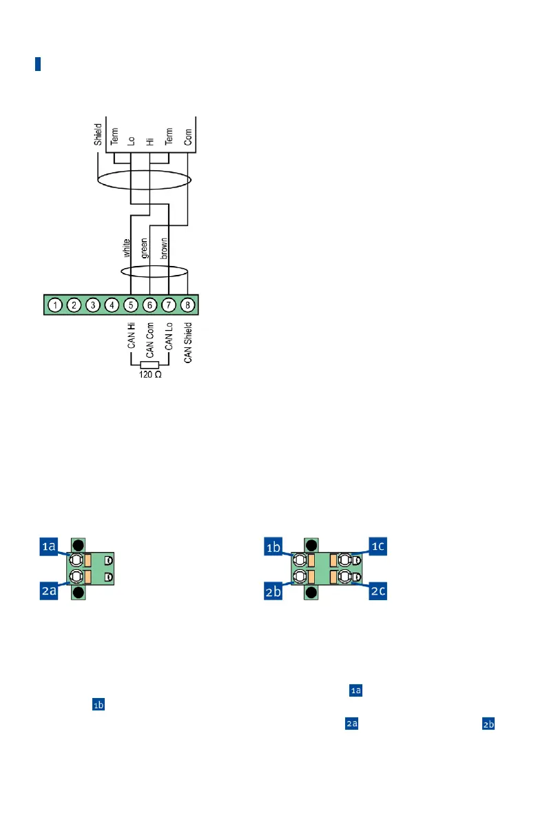
Connector for CAN
interface on PowerView3
CAN interface on the
ignition controller
PowerView3 Power Supply via the Ignition Controller
If you use a MOTORTECH ignition controller with a service cover and connector strip, you have
the option of supplying power to the PowerView3 via the ignition controller. A special connector
is included in the PowerView3's scope of supply. The connector for the voltage supply of the
ignition controller must be replaced by this one.
Connector supplied with
the ignition controller:
Connector supplied with
PowerView3:
Proceed as follows:
1. Disconnect the power supply to the ignition controller and, if necessary, to the PowerView3.
2. Remove the connector for the power supply from the ignition controller.
3. Negative terminal: Disconnect the conductor from the contact
and insert it into
contact
of the connector provided with the PowerView3.
4. Positive terminal: Disconnect the conductor from the contact
and insert it into contact
of the connector provided with the PowerView3.