7 Functions
Rev. 03/2019 67
Application of the ASO signal
The following example will illustrate the application of the ASO signal:
– Four-stroke engine with 6 cylinders
– Ignition angle 120° - 120°
Synchronization between MIC5 and Valve Controller
Cyl.
Ignition angle in
°crankshaft
ASO signal in
°crankshaft
Pulse duration in
μs
1 0/720 718 160
2 120 118 80
3 240 238 80
4 360 358 80
5 480 478 80
6 600 598 80
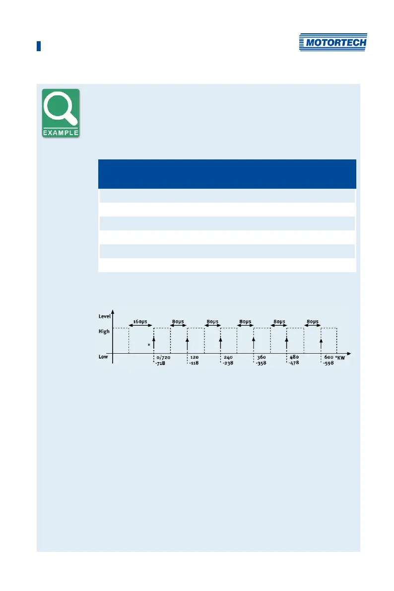
Schematic Representation (Standard Settings)
*
)
active edge
The valve controller should receive the active edge of the ASO signal before
the top dead center of a cylinder. The first pulse duration should be twice
as long and thus mark the beginning of a cycle. The ASO signal generated
by the MIC5 increases by 2° each time before the ignition signal from Low
to High, as can be seen in the schematic drawing. This edge is analyzed by
the valve controller as the active edge.
The ASO signal drops in accordance with the configured pulse duration
from High to Low before the active edge. The valve controller then has
already measured the pulse duration of the active edge and can provide
information on the allocation of the signal. In the example shown here, the
first cylinder is marked with a pulse width of 160 µs versus 80 µs for other
cylinders. If the valve controller measures a pulse width of 160 µs, the
subsequent signal is therefore allocated to the first cylinder. The next
signal then corresponds with the second cylinder in the ignition sequence,
etc.