8 Additional information
BU 0200 en-3118 261
Pos: 73 0 /Anlei tung en/El ektr onik/FU und Star ter/8 . Zus atzinfor mati one n/Red uziert e Ausga ngslei stu ng/_R eduzi erter Ausgang sstr om aufgrund der Drehzahl [SK 2xxE] @ 6\mod_1429263361868_388.docx @ 212088 @ 3 @ 1
8.4.6 Reduced output current due to speed
The size 1 – 3 devices are designed such that the waste heat that occurs can only be given off via the
housing in sufficient quantities if the frequency inverter with motor installation is also cooled by an
air flow. If this air flow is generated by a self-ventilated motor (impeller mounted on the motor shaft),
the strength of the air flow then depends on the motor speed. This means that as the motor speed
reduces, so does the air flow. Depending on the frequency inverter and the speed that is present,
appropriate restrictions in the possible output power (S1 operation) must be taken into consideration.
This restriction can be determined on the basis of the following graph. However, it must be taken into
consideration that the result that is determined can only be a rough estimate, since various influential
factors such as specific frequency inverter / motor combinations cannot also be taken into
consideration. More information can be found in the catalogue G4014
.
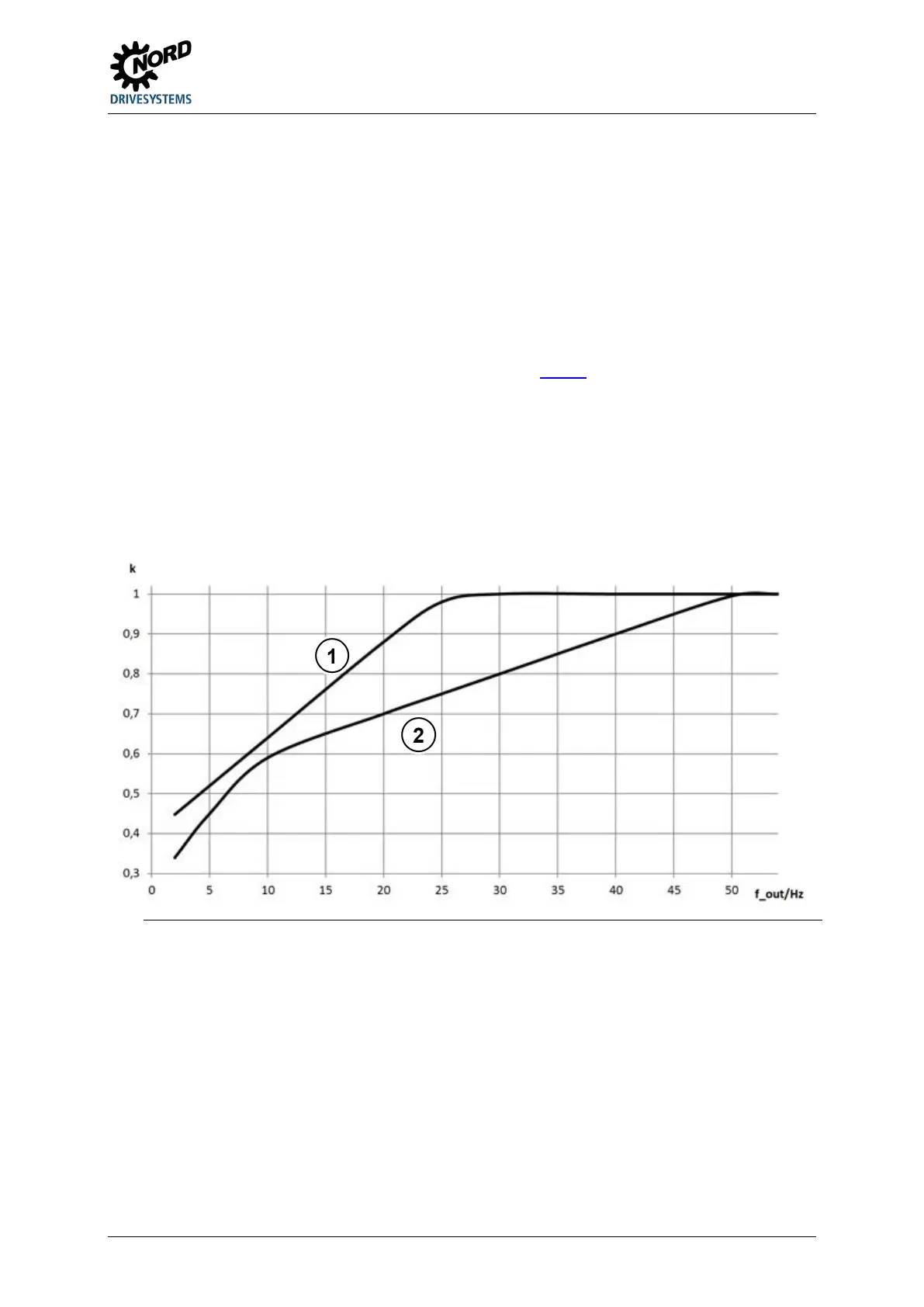
The "k" factor of the following graph must be multiplied by the nominal data of the frequency inverter
concerned, and therefore results in the possible continuous current or the possible continuous output
in S1 operation.
Example:
SK 200E-401-340A, I
nom
= 8.9 A, f_out: 20 Hz k=0.7
I = I
nom
x k I = 8.9 A x 0.7 = 6.2 A in S1 operation
1 =
All device sizes 1 to 3 except the devices from ( 2 )
2 =
SK 2xxE-111-323-A, SK 2xxE-221-323-A, SK 2xxE-401-323-A,
SK 2xxE-221-340-A, SK 2xxE-401-340-A, SK 2xxE-751-340-A
Figure 36: Derating factor "k" for motor installation (self-ventilated)
Pos: 73 1 /Allg emein/ Allg emeing ültig e Mod ule/---------Sei tenumbr uch ko mpakt --------- @ 13\mod_1476369695906_0.docx @ 2265495 @ @ 1

 Loading...


