NORDAC FLEX (SK 200E ... SK 235E) – Users Manual for Frequency Inverters
52 BU 0200 en-3118
Pos: 10 1 /Anlei tu nge n/El ektr oni k/FU un d St art er/2 . M on tage un d Inst all ati on/Z ub ehör/ Br ems wid erst an d/SK 1x0 E, SK 2 xxE /Bre ms wid erst and ( BW) (Ü bersc hrif t +) [ SK 1x0 E, SK 2xxE] @ 1\mod_1342513979710_388.docx @ 32688 @ 2 @ 1
2.3 Braking resistor (BW) - (from size 1)
During dynamic braking (frequency reduction) of a three-phase motor, electrical energy is returned to
the inverter if necessary. From size 1 and above, an internal or external braking resistor can be used
to avoid a shut-down of the device due to overvoltage. With this, the integrated brake chopper
(electronic switch) pulses the link circuit voltage (switching threshold approx. 420 V / 720 V
DC
,
depending on mains voltage) into the braking resistor. The braking resistor converts excess energy
into heat.
Pos: 10 2 /Anlei tung en/El ektr onik/FU und Star ter/1 . Allg emei nes /Sic herh eits - und I nstall atio nshin weise un d Warn- Gefahrenhinweise/neu/Warn- und Gefahrenhinweise/VORSICHT - Heiß e O ber fläc hen ( Br ems wider s tan d) @ 19\ mod_1511280417222_388.docx @ 2372139 @ @ 1
CAUTION
Hot surfaces
The braking resistor and all other metal components can heat up to temperatures above 70°C.
• Danger of injury due to local burns on contact.
• Heat damage to adjacent objects
Allow sufficient cooling time before starting work on the product. Check the surface temperatures with suitable
measuring equipment. Maintain an adequate distance to adjacent components or provide protection against
contact.
Pos: 103 /A nleit ung en/El e ktr onik /FU und Star ter /2. M ontag e u nd I nst alla tio n/Z ube hör/ Bre ms wider st and/ SK 1 x0E , SK 2xx E/IN FOR MA TION - Daten Bremswiderstand parametrieren [SK 200E] @ 21\mod_1528383930708_388.docx @ 2424981 @ @ 1
Parameterisation of braking resistor data
To protect the braking resistor against overload, the electrical data of the braking resistor which is used must be
parameterised in parameters P555, P556 and P557. With the use of an internal braking resistor (SK BRI4-…) this
is done by setting the DIP switch S1:8 ( Section
2.3.1)
Pos: 10 4 /Anlei tung en/El ektr onik/FU und Star ter/2 . Mon tage un d Install ati on/Z ub ehör/ Br ems wid erst an d/SK 1x0 E, SK 2 xxE /Int er ner Br em swi der stan d SK BR I4-. .. [SK 2xxE] @ 21\mod_1528365342363_388.docx @ 2424706 @ 35 @ 1
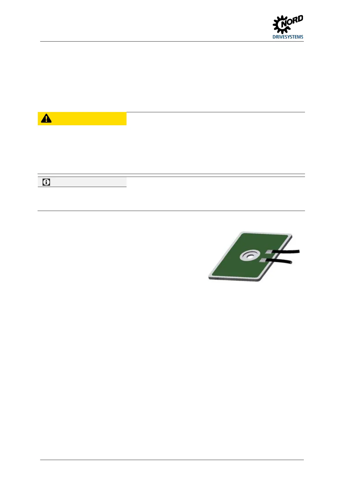
2.3.1 Internal brake resistor SK BRI4-…
The internal brake resistor can be used if only slight, short
braking phases are to be expected. For the individual power
ranges of size 4, the item includes a set of 2 brake resistors.
These must be connected in parallel and thereby achieve the
electrical data from the description of the material
installation location for the 2nd brake resistor is opposite the
installation location of the 1st brake resistor.
similar to Figure

 Loading...


