NORDAC FLEX (SK 200E ... SK 235E) – Users Manual for Frequency Inverters
106 BU 0200 en-3118
Pos: 23 5 /Anlei tu nge n/El ektr oni k/FU un d St art er/4 . I nbe tri ebn ahme/ SK 1xx E, S K 2 xxE, -FD S/In betrie bnahm e Gerät /DIP- Schal ter (S 1) [SK 2 xxE] @ 1\mod_1343219568354_388.docx @ 37376 @ 45 @ 1
">
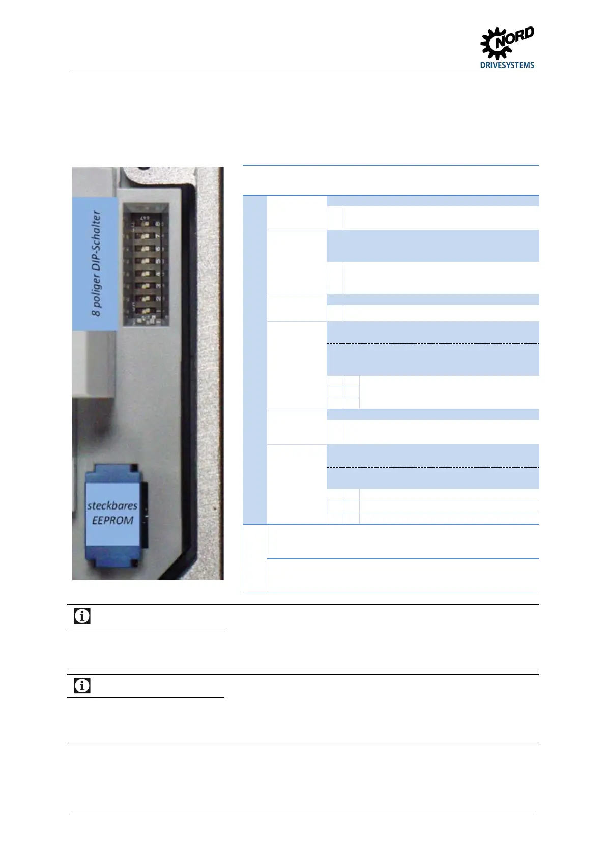
4.3.2.2 DIP switches (S1)
The DIP switches make it possible to carrying out commissioning without additional control units.
Further settings are made using the potentiometer on the top of the frequency inverter (P1 / P2,
SK 2x5E only).
Information
Factory setting, as delivered!
As delivered, all DIP switches are in the "0" ("off") position. Actuation takes place using the digital control signals
(P420 [01]-[04]) and the potentiometers P1 and P2 integrated in the FI (P400 [01]-[02]) (P1 / P2 with SK 2x5E
only).
IO bit factory settings:
For controlling the frequency inverter via In/Out bits (e.g.: AS-i, DIG In 1 - 4) typical values are pre-set in the
relevant parameters (P480) and (P481) (Details: Section 5 "Parameter").
These settings apply to both control via AS-i bits and BUS I/O bits.
Bit DIP switch (S1)
8
2
7
Int R
Brake
Internal brake
resistor
Internal brake resistor not existing
I
Internal brake resistor existing
( Section 2.3.1)
7
2
6
60Hz
1)
50/60Hz
operation
0
Motor data corresponding to the rated power
of the
FI in kW relative to 50 Hz, fmax = 50 Hz
I
Motor data corresponding to the rated power
of the
FI in hp relative to 60 Hz, fmax = 60 Hz
6
2
5
EEPROM copy
I EEPROM copy function active, once
5/4
2
4/3
I/O
Potentiometer
function, digital
inputs and AS
interface
0 0
Corresponding to P420 [1-4] and P400
[1-2]
or P480 [1-4] and P481 [1-4]
Further details in the next table.
(depends on the DIP3 "BUS")
3
2
2
Source control
word and
Corresponding to P509 and P510 [1] [2]
I
System bus (⇒ P509=3 and P510=3)
2/1
2
1/0
ADR
System bus
address/ baud
rate
0 0
Corresponding to P515 and P514 [32,
250kBaud]
A changed setting is applied the next time the mains is switched on.
Existing settings in parameters P201-P209 and P105 are overwritten!
up to firmware version 1.4 R1 the DIP switch designation was U/F. A
changeover between the control procedures (U/F / ISD control) has been
made possible via the DIP switch.

 Loading...


