2 Assembly and installation
BU 0200 en-3118 49
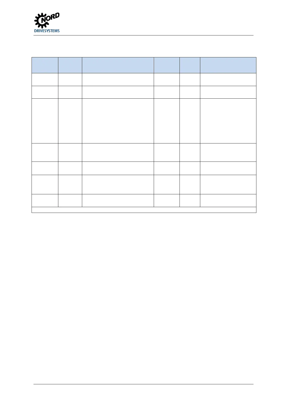
The preferred installation location for M12 sockets or connectors should be 4L or 4R. An additional
M32 hole (option location 9) is provided for the mains connection of size 4.
Option
location
Position Meaning Size
Size 1 - 3
Size
Size 4
Comments
Installation location for customer
interfaces SK CU4-…
mounting location for internal
braking resistor SK BRI4-…
3* on side Mounting location for
• External brake resistor SK
BRE4-…
• external technology units
SK TU4-…
• Operating options
• Power connector
Not available if location 3
is occupied or SK TU4-…
is fitted.
4*
5*
on side Cable gland M16 M16 Not available if SK TU4-…
is fitted.
7*
8*
Not available if location 3
is occupied by SK BRE4
or SK TU4-… is fitted
Preferably used for mains
cable
* R and L (right and left side)
Pos: 95 /A llg em ein/ Allg em eing ülti ge M od ule/ ---------Seite numbruc h kom pakt --------- @ 13\mod_1476369695906_0.docx @ 2265495 @ @ 1

 Loading...


