2 Assembly and installation
BU 0200 en-3118 39
Pos: 75 /A nl eitu nge n/El ek tro nik/FU u nd S tart er/ 2. M o ntag e un d Ins tall ati on/M o ntag e/M otor mo ntag e - Standard [SK 1xxE, SK 2xxE]/Montage Isolierplatte – Baugr öße 4 [SK 2 xxE] @ 10 \mod_1456819981747_388.docx @ 310876 @ 35 @ 1
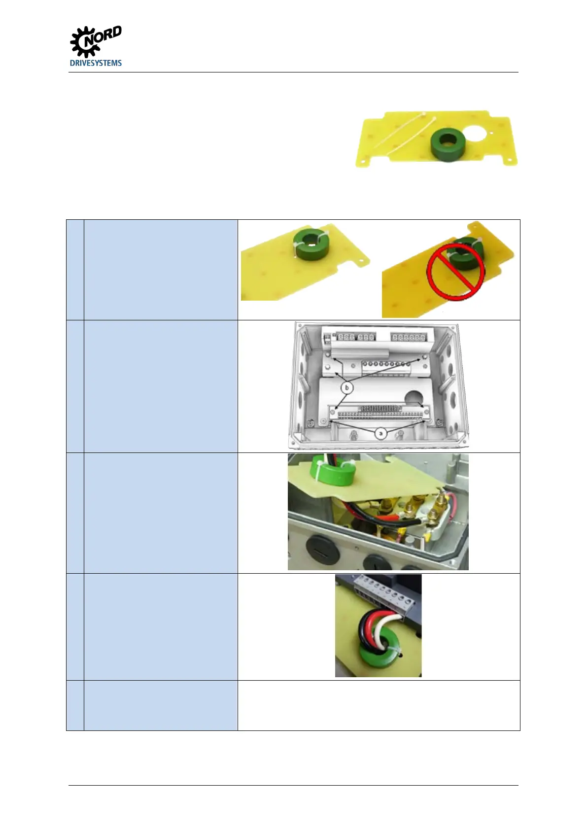
2.1.1 Installation of insulating plate – size 4
As of hardware status EAA of the frequency inverter (suitable
connecting unit hardware status EA), a ring core must be fitted
to the insulating plate (motor terminal cover). The ring core and
the required fastening materials are included in the scope of
delivery of the connecting unit.
The ring core is required to ensure that the EMC requirements are adhered to.
Assembly sequence
1.
Secure ring core with cable ties as
shown in left-hand illustration (pay
attention to insulating plate
alignment).
Remove terminal strips (b).
Connect wiring harness (motor
cable) and lead through the ring core
attached to the insulating plate.
4.
Wire motor cable to connecting
terminals U – V – W of the relevant
terminal strip.
• Fit insulating plate (see
illustration in step 2 – (a)).
• Fit terminal strips (see illustration
in step 2 – (b)).
Pos: 76 /A llg em ein/ Allg em eing ülti ge M od ule/ ---------Seite numbruc h kom pakt --------- @ 13\ mod_1476369695906_0.docx @ 2265495 @ @ 1

 Loading...


