4 Commissioning
BU 0200 en-3118 121
Pos: 263. 10 / Anl eit unge n/ Elek tro nik/F U u nd St arter/ 4. Inb etri eb nah me/A S-I nterf ace [all e Gerät e]/Bu saufba u und To polog ie_01 [ SK 1xx E, SK 2xxE , SK xxxE- FDS] @ 9\mod_1443522627536_388.docx @ 247431 @ 3 @ 1
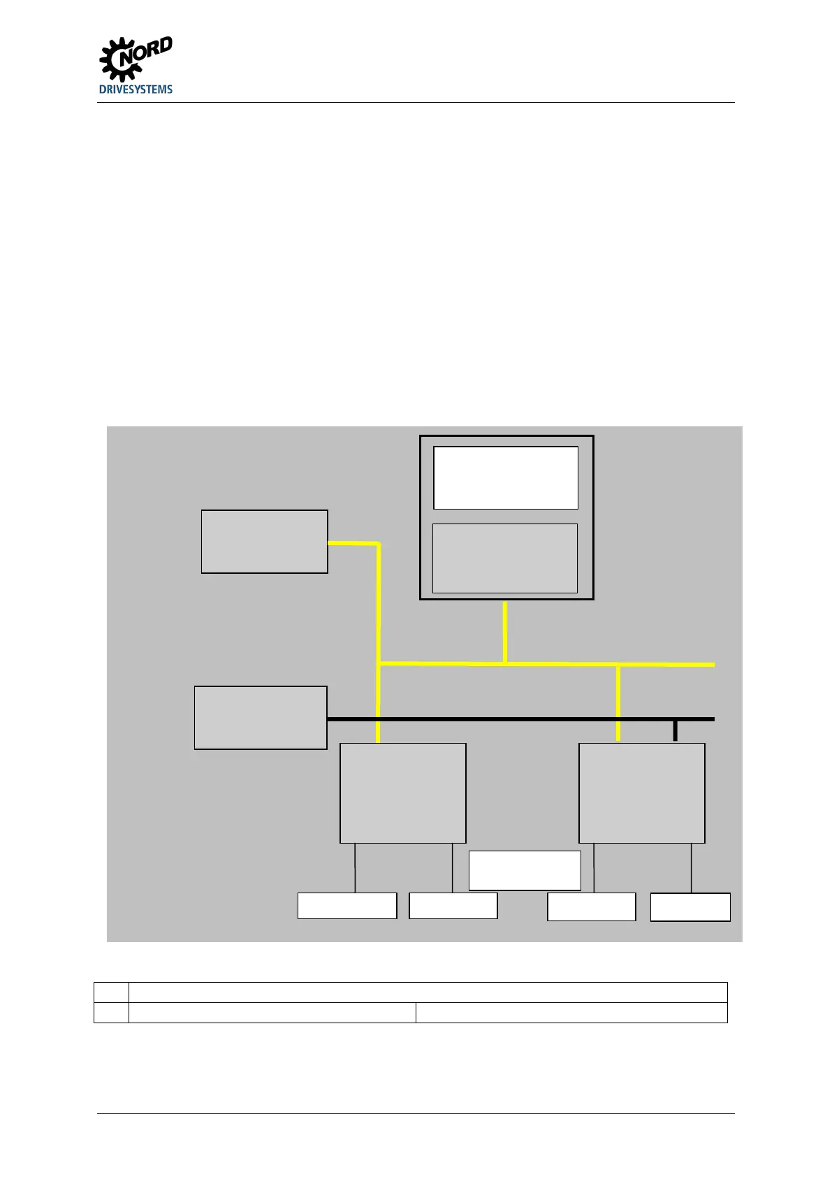
4.5.3 Bus structure and topology
The AS Interface network must be set up in any form (line, star, ring and tree structure) and is
managed by an AS interface master as the interface between the PLC and slaves. Additional slaves
can be added to an existing network at any time, up to a limit of 31 standard slaves or 62 A/B slaves.
The slaves are addressed by the master or an appropriate addressing device.
An AS-i master communicates independently and exchanges data with the connected AS-i slaves.
Normal power units may not be used in the AS interface network. Only a special AS interface power
unit may be used for the power supply for each AS interface connector. This AS interface power
supply is directly connected to the yellow standard cable (AS-i(+) and AS-i(-) cable) and should be
positioned as close as possible to the AS-i master in order to keep the voltage drop small.
In order to avoid problems, the PE connection of the AS interface power supply (if present) must
be earthed.
The brown AS-i(+) and the blue AS-i(-) wire of the yellow AS interface cable must not be earthed.
Pos: 263. 11 / Anl eit unge n/ Elek tro nik/F U u nd St arter/ 4. Inbetriebnahme/AS-Inter face [al le Ger äte]/ Busauf bau u nd Topol ogie _02 [SK 1 x5E, SK 2 xxE, SK x xxE-FDS ] @ 9 \mod_1443526149397_388.docx @ 247495 @ @ 1
Pos: 263. 12 / Anl eit unge n/ Elek tro nik/F U u nd St arter/ 4. Inb etri eb nah me/A S-I nterfa ce [all e Gerät e]/Bu saufba u und To polog ie_03 [S K 2xx E] @ 9\mod_1444311533459_388.docx @ 249020 @ @ 1
SK 225E-… / SK 235E-…-AUX and -AXB
24 V DC auxiliary energy at terminals 44/40
Pos: 263. 13 / All ge mei n/Al lgem ei ngült ige M o dul e/---------Seitenumbruch kompakt --------- @ 13\mod_1476369695906_0.docx @ 2265495 @ @ 1
AS interface
master
AS interface
power unit
Controller /
automation unit
24 V power supply
for auxiliary energy
AS interface
Slave
1)
AS interface
Slave
2)
yellow cable
24 V auxiliary supply,
black cable

 Loading...


