NORDAC FLEX (SK 200E ... SK 235E) – Users Manual for Frequency Inverters
58 BU 0200 en-3118
Pos: 11 8 /Anlei tung en/El ektr onik/FU und Star ter/2 . Mon tage un d Install atio n/Ele ktrisc her Ans chlus s/Ele ktris cher Ans chl uss_0 1 (Überschrift) [SK 1xxE, SK 2xxE, SK 5xxE, SK xxxE-FD S] @ 12\mod_1467020207250_388.docx @ 333210 @ 2 @ 1
2.4 Electrical Connection
Pos: 11 9 /Anlei tung en/El ektr onik/FU und Star ter/1 . Allg emei nes/Sic herh eits- und Ins tall ations hinwei se un d Warn- Gefahrenhinweise/neu/Warn- und Gefahrenhinweise/WARNUNG - Elektrischer S chlag (Span nung, au ch wenn Gerät auß er Betr ieb) [ dezen tral a ußer FDS] @ 19\mod_1511356071949_388.docx @ 2372289 @ @ 1
WARNING
Electric shock
Dangerous voltages can be present at the mains input and the motor connection terminals even when the device
is not in operation.
• Before starting work, check that all relevant components (voltage source, connection cables, connection
terminals of the device) are free of voltage using suitable measuring equipment.
• Use insulated tools (e.g. screwdrivers).
• DEVICES MUST BE EARTHED.
Pos: 12 0 /Anlei tung en/El ektr onik/FU und Star ter/2 . Mon tage un d Install atio n/Ele ktrisc her Ans chlus s/Ele ktris cher Ans chl uss_02 [SK 1xxE, SK 2xxE, SK 5xxE; -FD S] @ 19\mod_1511361579868_388.docx @ 2372329 @ @ 1
Information
Temperature sensor and PTC (TF)
As with other signal cables, thermistor cables must be laid separately from the motor cables Otherwise the
interfering signals from the motor winding that are induced into the line affect the device.
Ensure that the device and the motor are specified for the correct supply voltage.
Pos: 12 1 /Anlei tung en/El ektr onik/FU und Star ter/2 . Mon tage un d Install atio n/Ele ktrisc her Ans chl uss/ Ele ktr isch er Ans chl uss _Erg änz ung 1 [SK 2x xE] @ 7 \mod_1434463656020_388.docx @ 226135 @ @ 1
In order to access the electrical connections, the SK 2xxE must be removed from the SK TI4-…
connection unit ( Section 2.1.2 "Motor installation work operations").
One terminal block is provided for the power connections and one for the control connections.
The PE connections (device-earth) are inside the cast housing of the connecting unit on the base. A
contact is available on the power terminal block for size 4.
Pos: 12 2 /Anlei tung en/El ektr onik/FU und Star ter/2 . Mon tage un d Install ation/Elektri scher Anschl uss/Elektrisch er Anschl uss_Ergänzung 2 [SK 1xxE , SK 2 xxE] @ 8\mod_1439219159130_388.docx @ 236273 @ @ 1
The terminal strip assignments differ according to the version of the device. The correct assignment
can be found on the inscription on the respective terminal or the terminal overview plan printed inside
the device.
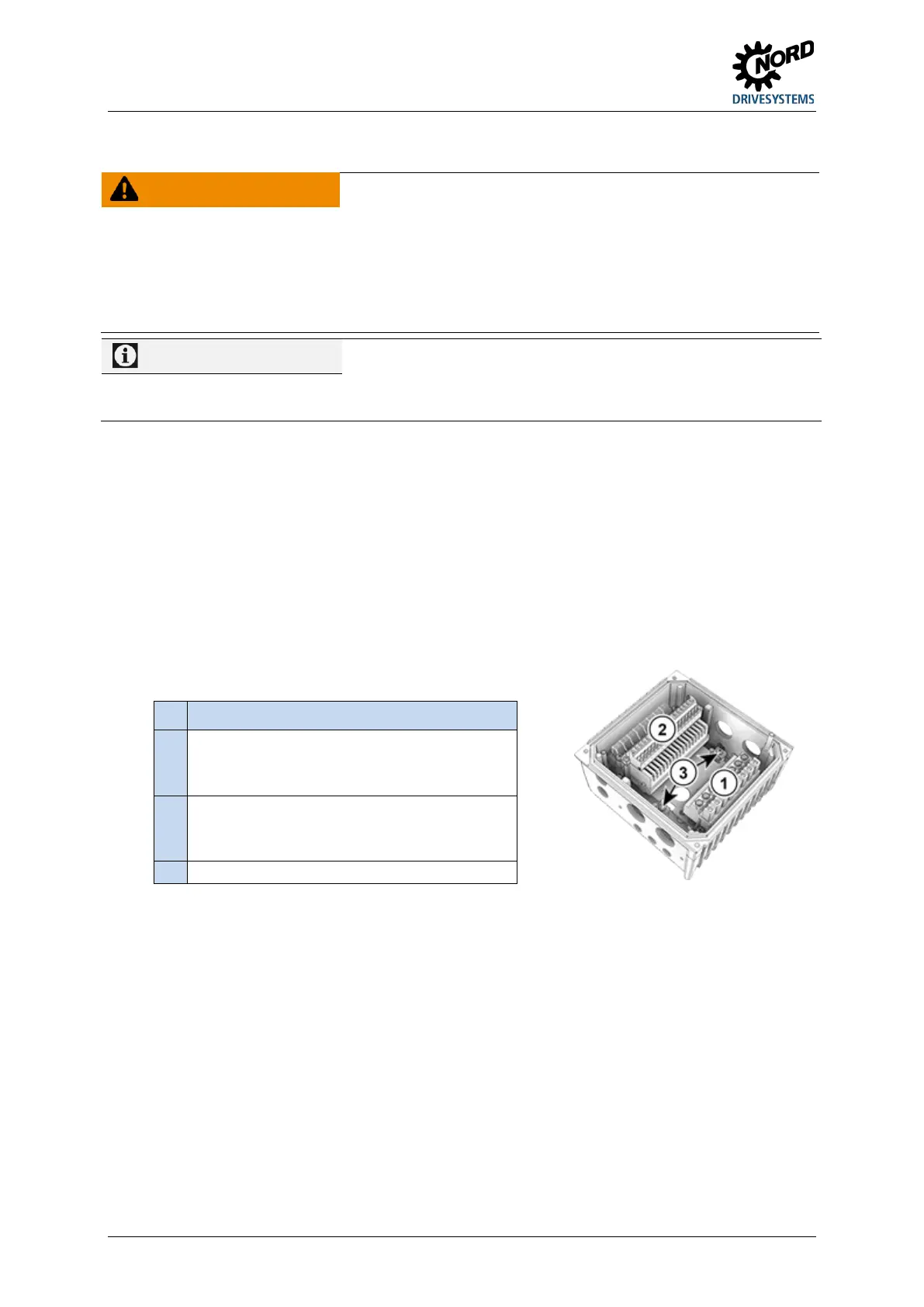
Pos: 12 3 /Anlei tung en/El ektr onik/FU und Star ter/2 . Mon tage un d Install atio n/Ele ktrisc her Ans chlus s/Ele ktris cher Ans chl uss_Er gänz ung 3 [SK 2x xE] @ 8 \mod_1439287784030_388.doc x @ 23637 3 @ @ 1
Connecting terminals for
Control lines
Electromechanical brake
Pos: 12 4 /Allgemein/Allgemeingültige Module/---------Seiten umbruc h komp akt --------- @ 13\mod_1476369695906_0.docx @ 2265495 @ @ 1

 Loading...


