3 Display, operation and options
BU 0200 en-3118 85
3 Display, operation and options
Pos: 18 0 /Anlei tung en/El ektr onik/FU und Star ter/3 . Anzei ge, Be dienu ng und Op tione n/Anz eige , Bedie nung un d Optio nen_ 01 [SK 2x xE] @ 8\mod _1441111756429_388.docx @ 238817 @ @ 1
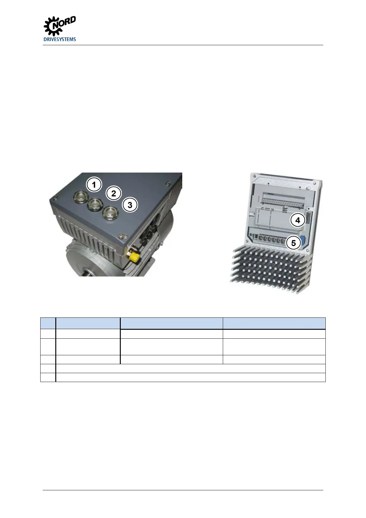
As supplied, without additional options, the diagnostic LEDs are externally visible. These indicate the
actual device status. 2 potentiometers (only SK 2x5E) and 8 DIP switches (S1) are provided in order
to set the most important parameters. In this minimal configuration no other adapted parameters are
stored in the external (plug-in) EEPROM. The only exception are data concerning operating hours,
faults and fault circumstances. This data can only be saved in the external EEPROM (memory
module) up to firmware version V1.2. As of firmware version 1.3, this data is saved in the internal
EEPROM of the frequency inverter.
The memory module (external EEPROM) can be pre-parametrised independently of the frequency
inverter using programming adapter SK EPG-3H.
Figure 18: SK 2xxE (size 1), top view
Figure 19: SK 2xxE (size 1), internal view
No. Designation SK 2x0E size 1 … 3 SK 2x5E and SK 2x0E size 4
(250 Ω for current setpoint)
Diagnostic opening 3 Diagnostic LEDs Potentiometers (P1 / P2)
Pos: 18 1 /Allg emein/ Allg emeing ültig e Mod ule/---------Sei tenumbr uch ko mpakt --------- @ 13\mod_1476369695906_0.docx @ 2265495 @ @ 1

 Loading...


