NORDAC FLEX (SK 200E ... SK 235E) – Users Manual for Frequency Inverters
122 BU 0200 en-3118
Pos: 263. 14 / Anl eit unge n/ Elek tro nik/F U u nd St arter/ 4. Inbetriebnahme/AS-Inter face [al le Ger äte]/I nbetr iebn ahme [S K 1xxE, SK 2xxE, SK xxxE-FD S] @ 2\mod_1347364111083_388.docx @ 45181 @ 3 @ 1
4.5.4 Commissioning
Pos: 263. 15 / Anl eit unge n/ Elek tro nik/F U u nd St arter/ 4. Inb etri eb nah me/A S-I nterfa ce [all e Gerät e]/An schlus s_01 [SK 1xxE, SK 2 xxE] @ 8 \mod_1443084432375_388.docx @ 245730 @ 4 @ 1
4.5.4.1 Connection
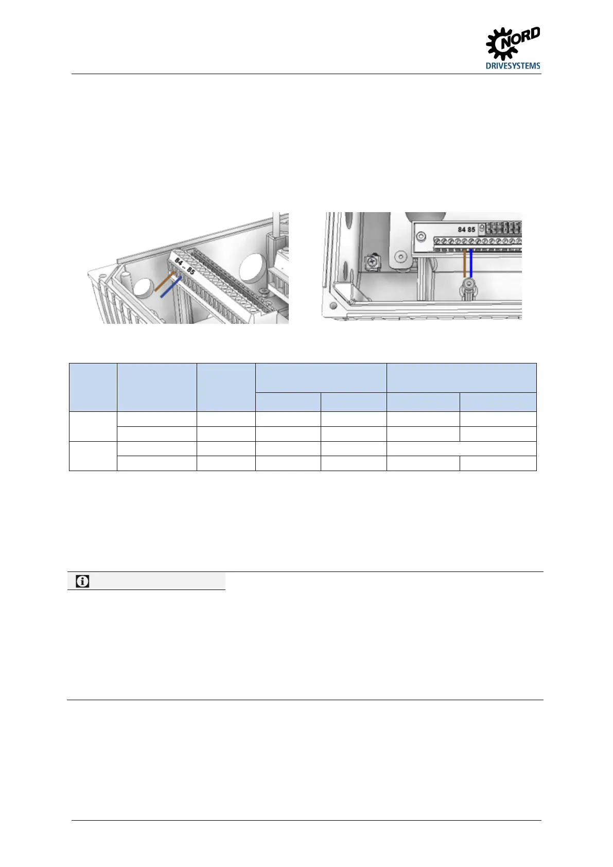
Connection of the AS interface cable (yellow) is made via terminals 85/85 of the terminal strip and can
optionally be made to an appropriately labelled M12 flange plug connector (yellow)
Details of control terminals ( Section 2.4.3.1 "Control terminal details ")
Details of connector ( Section 3.2.3 "plug connectors")
Pos: 263. 16 / Anl eit unge n/ Elek tro nik/F U u nd St arter/ 4. Inb etri eb nah me/A S-I nterfa ce [all e Gerät e]/An schlus s_02 [S K 2xxE ] @ 9\mod_1443187398513_388.docx @ 246514 @ @ 1
Figure 28: Connecting terminals AS-i, left size 1 – 3, right size 4
Pos: 263. 17 / Anl eit unge n/ Elek tro nik/F U u nd St arter/ 4. Inb etri eb nah me/A S-I nterfa ce [all e Gerät e]/An schlus s_03 [S K 2xxE ] @ 9\mod_1443424948992_388.docx @ 246998 @ @ 1
Type Special version Size
AS Interface connection
Control voltage connection
e.g. AUX line of a PELV
AS-i(+) AS-i(-) 24 V DC GND
SK 220E,
SK 230E
SK 225E,
SK 235E
Size 1 – 3 84 85
Connection not permitted!
1) The control section of the frequency inverter is not supplied from the AS interface line. The required auxiliary voltage for this is generated
by the device itself.
Connection possible, but not required.
Table 12: AS Interface, connection of signal and supply lines
Pos: 263. 18 / Anl eit unge n/ Elek tro nik/F U u nd St arter/ 4. Inb etri eb nah me/A S-I nterfa ce [all e Gerät e]/An schlus s_04 [S K 1xxE , SK 2xxE ] @ 9\mod_1443431797146_388.docx @ 247029 @ @ 1
If the AS interface ("yellow cable") is not used, the normal connection requirements for the device
apply ( Section 2.4.3.1 "Control terminal details ").
Pos: 263. 19 / Anl eit unge n/ Elek tro nik/F U u nd St arter/ 4. Inb etri eb nah me/A S-I nter face [all e Ger äte]/ An schl uss _05 ( Inf or mati on) [SK 2x xE] @ 2 1\mod_1528385043990_388.docx @ 2425017 @ @ 1
24 V DC / AS-Interface (SK 225E/ SK 235E, except -AUX, -AXB)
With the use of the yellow AS interface line:
– the supply voltage (26.5 - 31.6 V DC) for the use of the digital inputs or other external peripherals (e.g.
activators) can be obtained from terminals 44/40. The permissible total current for this is limited to
60 mA!
The terminal "44" is protected against short circuit. In case of an overload it will switch off by a thermal
fuse element. After a cooling time that depends on the ambient conditions, the fuse will reset.
– no voltage source may be connected to terminals 44/40,
– the frequency inverter is supplied via the yellow AS-i line.
Pos: 263. 20 / All ge mei n/Al lgem ei ngült ige M o dul e/---------Seitenumbruch kompakt --------- @ 13\mod_1476369695906_0.docx @ 2265495 @ @ 1

 Loading...


