NORDAC FLEX (SK 200E ... SK 235E) – Users Manual for Frequency Inverters
74 BU 0200 en-3118
Pos: 16 7 /Anlei tung en/El ektr onik/FU und Star ter/2 . Mon tage un d Install atio n/Ele ktrisc her Ans chlus s/Dr ehgeb er/F arb- und K onta ktbel eg ung für Inkr e ment aldr ehg eber (HT L) [SK 2xx E] @ 1 9\mod_1511782908220_388.docx @ 2372936 @ 2 @ 1
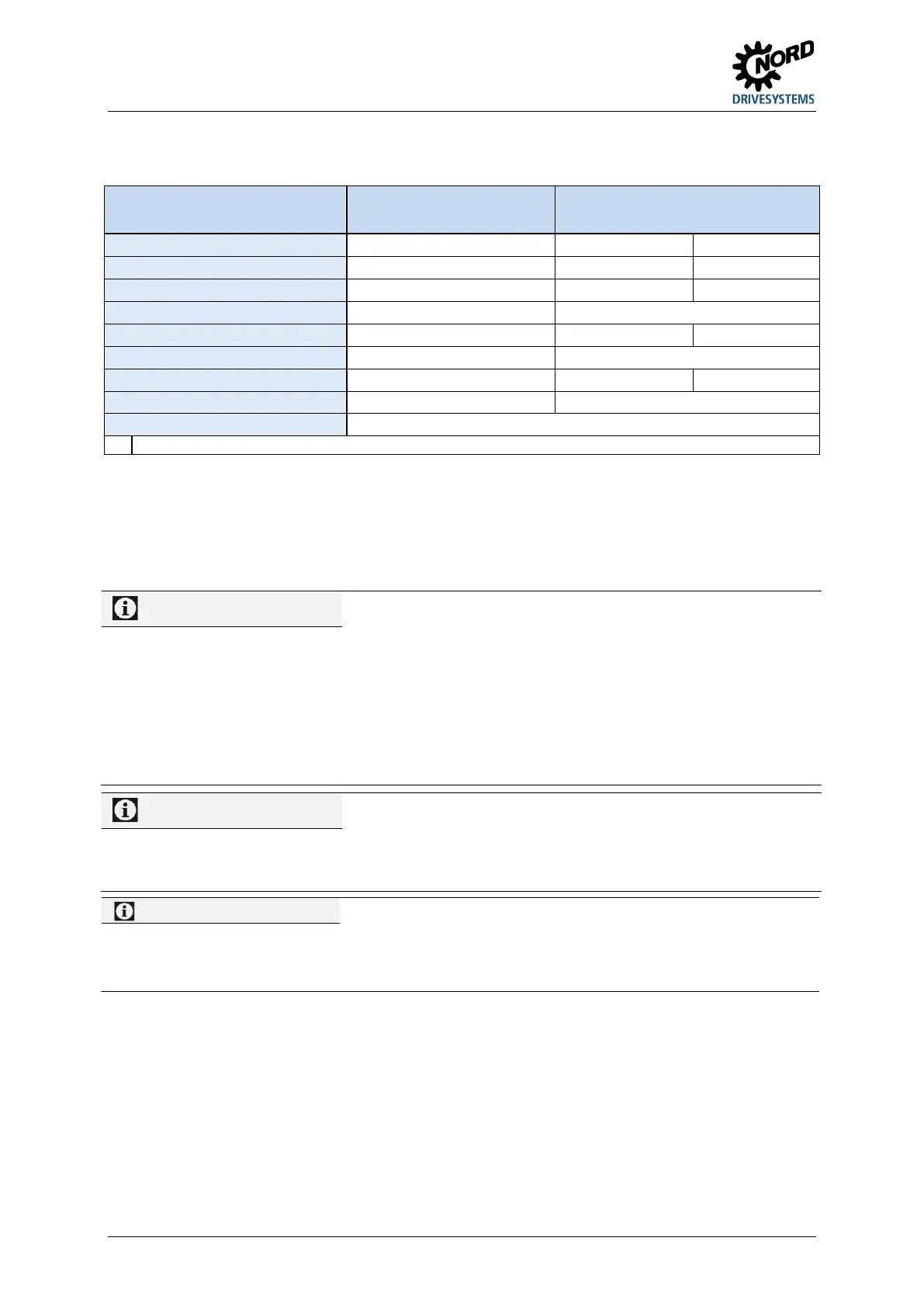
2.5 Colour and contact assignments for the incremental encoder (HTL)
Function
Wire colours
for incremental encoders
1)
Assignment for SK 2xxE
Track A inverse (A /) green --
Track 0 red 21 DIN1
Cable shield Large-area connection to frequency inverter housing.
The wire colours depend on the type of encoder and may differ. Please note the encoder data sheet!
Note the current consumption of the encoder (normally up to 150 mA) and the permissible load on the
voltage source.
Only digital inputs DIN 2 and DIN 3 are in a position to process the signals of an HTL encoder. For the
use of an encoder, parameters (P300) and/or (P600) must be activated according to requirements
(speed feedback / servo mode or positioning).
Pos: 16 8 /Anlei tung en/El ektr onik/FU und Star ter/1 . Allg emei nes/Sic herh eits- und Ins tall ations hinwei se un d Warn- Gefahrenhinweise /ne u/War n- un d Gefa hren hinwei se/Inf ormati on - Do ppel belegu ng DIN 2 u nd DIN 3 [S K 2xxE] @ 19 \mod_1511860681545_388.docx @ 2373609 @ @ 1
Information
DIN 2 and DIN 3 double allocation
The digital inputs DIN2 and DIN3 are used for 2 different functions:
1. For digital functions which can be parameterised (e.g. “enable left”),
2. For evaluation of an incremental encoder.
Both functions are coupled by an "OR" link.
Evaluation of an incremental encoder is
always activated. This means that if an incremental encoder is
connected, it must be ensured that the digital functions are disabled (Parameter (P420 [-02] and [-03]) or via DIP
switch (chapter 4.3.2.2)).
Pos: 16 9 /Anlei tung en/El ektr onik/FU und Star ter/1 . Allg emei nes/Sic herh eits- und Ins tall ations hinwei se un d Warn- Gefahrenhinweise/neu/Warn- und Ge fahr enhin weise /Inf ormati on - Drehrichtung bzw Störung des Gebersignals (Dr ehgeb er) [SK 2 xxE, SK 2x xE-FDS , +?] @ 19 \mod_1511860695438_388.docx @ 2373645 @ @ 1
Information
Rotation direction
The "counting direction" of the incremental encoder must correspond to the direction of rotation of the motor. If the
two directions are not identical, the connections of the encoder tracks (Track A and Track B) must be switched.
Alternatively, the resolution (pulse number) of the encoder in P301 can be set with a negative prefix.
Wires that are not required (e.g. Track A inverse / B inverse) must be isolated.
Otherwise, if these wires come into contact with each other or the cable shield, short-circuits can occur that can
cause encoder signal problems or destruction of the encoder.
Pos: 17 0 /Anlei tung en/El ektr onik/FU und Star ter/2 . Mon tage un d Install atio n/Ele ktrisc her Ans chlus s/Dr ehgeb er/F arb- und K onta ktbeleg ung für Inkrementaldrehgeber (HTL)_Ergänzung [SK 2xxE] @ 11\mod_1458311618705_388.docx @ 314437 @ @ 1
If the rotary encoder has a zero track, this must be connected to digital input 1 of the device. The zero
track is read out by the frequency inverter if parameter P420 [-01] has been set to function "43".
Pos: 17 1 /Allg emein/ Allg emeing ültig e Mod ule/---------Sei tenumbr uch ko mpakt --------- @ 13\mod_1476369695906_0.docx @ 2265495 @ @ 1

 Loading...


