NORDAC FLEX (SK 200E ... SK 235E) – Users Manual for Frequency Inverters
40 BU 0200 en-3118
Pos: 77 /A nl eitu nge n/El ek tro nik/FU u nd S tart er/ 2. M o ntag e un d Ins tall ati on/M o ntag e/M otor mo ntag e - Standard [SK 1xxE, SK 2 xxE]/ Arb eitsg äng e f ür di e M otor m ontag e [ SK 2 xxE ] @ 1\ mod_1341488911979_388.docx @ 29975 @ 3 @ 1
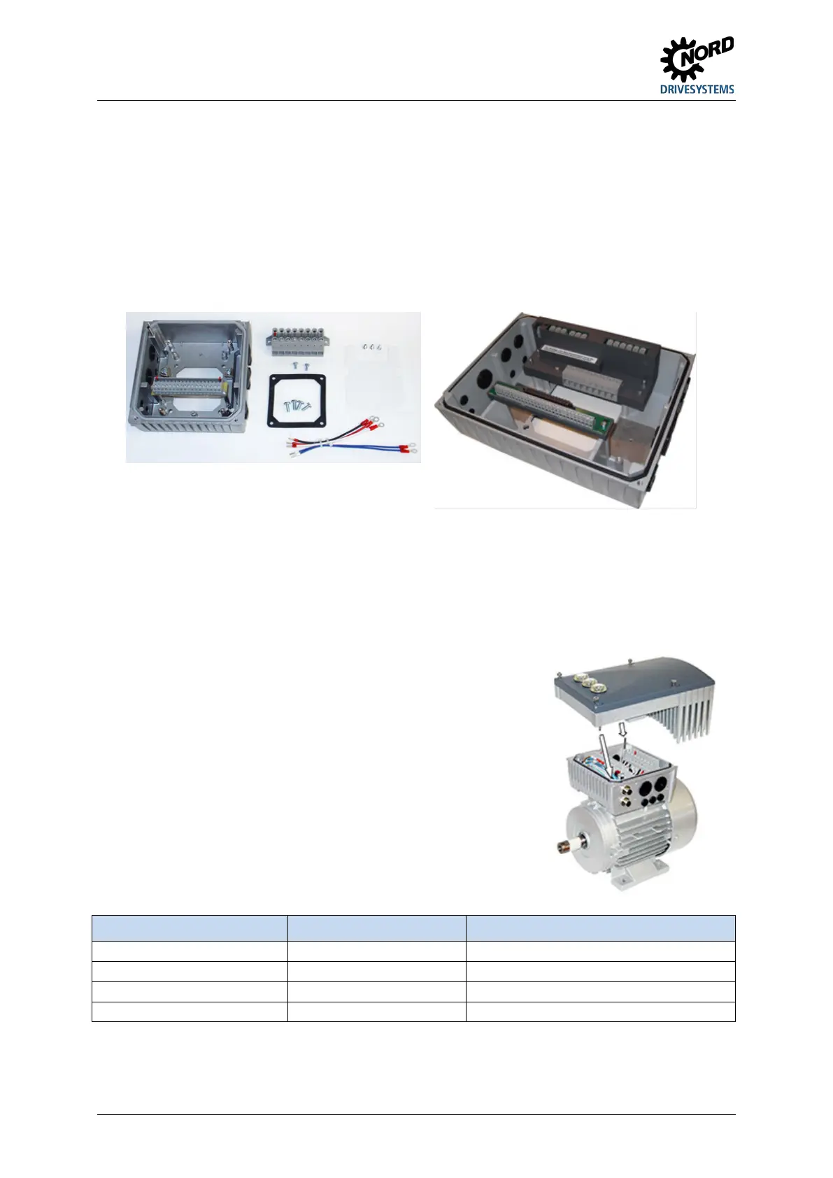
2.1.2 Motor installation work operations
If necessary, remove the original terminal box from the NORD motor, so that only the base of the terminal
box and the motor terminal block remain.
2. Set the bridges for the correct motor circuit at the motor terminal block and connect the pre-fabricated
cables for motor and PTC connections to the respective connection points of the motor.
Mount the connecting unit on the terminal box base of the NORD motor using the existing screws and seal
as well as the enclosed toothed / contact washers. When doing this, align the housing so that the rounded
side is facing in the direction of the A bearing shield of the motor. Carry out mechanical adaptation using the
"Adapter kit" (
2.1.2.1 "Adapters for different motors"). It must generally be checked whether motors
made by other manufacturers can be connected.
Figure 4: Connecting unit size 1 … 3 Figure 5: Connecting unit size 4
Fix insulating plate above the motor terminal block.
– Size 4: Attach ring core to insulating plate ( Section 2.1.1 "Installation of insulating plate – size 4").
Screw on the power terminal block above this using 2x M4x8 screws and the plastic washers. (Size 4: 3x
M4 cap nuts).
Make the electrical connections. For the cable gland of the connecting cable, appropriate screwed
connections for cable cross-section must be used.
Fit the frequency inverter to the connection unit With sizes 1 to 3,
special attention must be paid to correct contacting of the PE pins.
These are located diagonally in 2 corners of the frequency inverter and
the connection unit.
In order to ensure that the protection class for which the device is
intended is achieved, it must be ensured that all fastening screws that
attach the frequency inverter to the connecting unit are tightened
crosswise, step-by-step and with the torques stated in the table below.
The cable screw connections that are used must at least correspond
with the protection class of the device.
Size SK 2xxE Screw size Tightening torque
Size 3 M5 x 45 2.0 Nm ± 20 %
Pos: 78 /A llg em ein/ Allg em eing ülti ge M od ule/ ---------Seite numbruc h kom pakt --------- @ 13\ mod_1476369695906_0.docx @ 2265495 @ @ 1

 Loading...


