3 Display, operation and options
BU 0200 en-3118 91
Pos: 19 6 /Anl eitu ngen/El ektr onik/ FU und St arter /3. Anz eige, Bedie nung un d Optio nen/Op tione n [SK 1 xxE, SK 2x xE]/E xtern e Techn ologie boxe n SK TU 4 … [SK 1xx E, S K 2 xxE] @ 1\mod_1342689639572_388.docx @ 35158 @ 3 @ 1
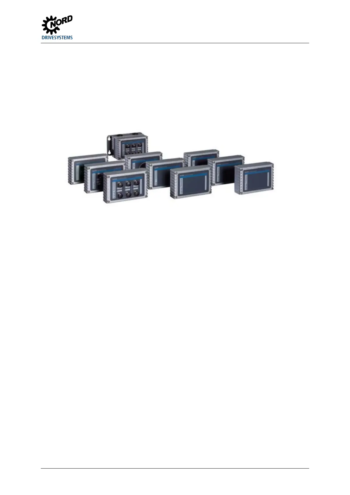
3.2.2 External technology units SK TU4-… (module attachment)
External technology units allow the scope of functionality of the devices to be extended in a modular
way.
Depending on the type of module, different versions are available (differentiated according to IP
protection class, with/without connector etc.). They can be fitted directly to the device using the
relevant connection unit or in the vicinity of the device using an optional wall mounting kit.
Each SK TU4-… technology unit requires an associated SK T14-TU-… connection unit.
Figure 23: external technology units SK TU4-… (example)
Pos: 19 7 /Anlei tung en/El ektr onik/FU und Star ter/3 . Anzei ge, Be dienu ng und Op tione n/Op tionen [ SK 1xx E, SK 2xxE ]/Ext erne T echnologieboxen SK TU4 …_01 [SK 1x0E, SK 2xxE] @ 8\mod_1441204686741_388.docx @ 239376 @ @ 1
With the bus modules or the I/O extension, it is possible to access the system bus via the RJ12 socket
(behind a transparent screw gland (diagnostics glass)) and therefore access all active devices that are
connected to it (frequency inverters, other SK xU4 modules) using ParameterBox SK PAR-3H or a PC
(NORD CON software).
The bus modules require a 24 V power supply. If the power is on the bus modules are ready, even if
the frequency inverter is not in operation.
Pos: 19 8 /Allg emein/ Allg emeing ültig e Mod ule/---------Sei tenumbr uch ko mpakt --------- @ 13\mod_1476369695906_0.docx @ 2265495 @ @ 1

 Loading...


