NORDAC FLEX (SK 200E ... SK 235E) – Users Manual for Frequency Inverters
48 BU 0200 en-3118
Pos: 93 /A nl eitu nge n/El ek tro nik/FU u nd S tart er/ 2. M o ntag e un d Ins tall ati on/M o ntag e/M otor mo ntag e - St andar d [SK 1xxE, S K 2xxE]/Montage Optionsbaugruppen [SK 1xxE / SK 2xxE] @ 1\mod_1342690542275_388.docx @ 35191 @ 2 @ 1
2.2 Installation of optional modules
Modules must not be inserted or removed unless the device is free of voltage. The slots may only be
used for the intended modules.
Pos: 94 /A nl eitu nge n/El ek tro nik/FU u nd S tart er/ 2. M o ntag e un d Ins tall ati on/M o ntag e/M otor mo ntag e - St and ard [SK 1 xxE, SK 2 xxE]/ Optio nsplätz e der A nschlus sei nheit „SK TI4 …“ [SK 2xxE] @ 1\mod_1342510716734_388.docx @ 32615 @ 3 @ 1
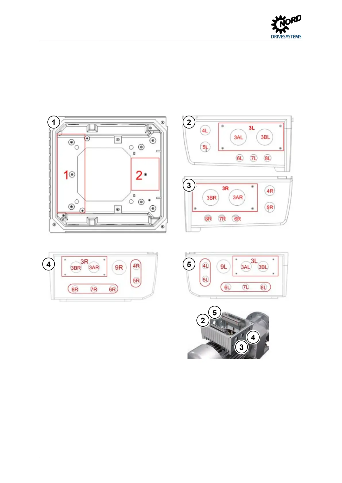
2.2.1 Option locations on the device
The installation locations for optional modules are not directly on the frequency inverter but on its
connecting unit.
View from left, size 1 to 3
View from right, size 1 to 3
View from right, size 4
View from left, size 4
Figure 15: Option locations on the connection unit
The various installation locations for the optional modules are displayed in the above-mentioned
drawings. Option location 1 is used for implementation of an internal bus module or an internal power
supply (not SK 2x0E). An internal brake resistor can be implemented at option location 2. External bus
modules, 24 V DC power supplies (not SK 2x0E) or potentiometer modules can be fitted at option
location 3L or 3R. The same applies to external brake resistors. Option locations 4 and 5 are used to
install M12 sockets or connectors. Additional extensions from M12 to M16 are required at locations 6,
7 and 8 for sizes 1 to 3 so that M12 sockets and connectors can also be fitted here. Option locations 6
- 8 are also M16 for size 4 devices. Only one option can be attached in an option location, of course.

 Loading...


