Operation
4-15
P/N 7135268B
E 2008 Nordson Corporation
PURBlue EC
Heated Components
The melter has three groups of heated components: These are the tank
group (grid and reservoir), the hose group that contains the hopper, and the
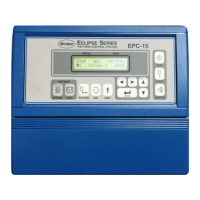
gun group. Component groups are shown on the control panel as
component keys (Fig. 4-6).
Fig. 4-6
Heated components within each group are identified by their position
number.
Hose and gun position numbers are automatically assigned based on the
hose/gun receptacle they are connected to. For example, the position
numbers of a hose/gun pair that is connected to the second receptacle
would be hose position 2 and gun position 2.
The position of the hopper is fixed with hose number 5.
NOTE: If individual components are disconnected from the melter, their
setpoint temperatures should be set to 0 (Off) to prevent an F1 fault.
Observe for Auxiliary Devices
In some installations, auxiliary devices (e.g. a heated air manifold) may be
connected to a hose/gun receptacle. The control panel will identify such
auxiliary devices as a hose or gun, regardless of what the device actually is.
Meaning of LED Colors of Component Keys
The LEDs on each component key will change from green to yellow if any
component in the group drops more than 3 _C (5 _F) below its assigned
setpoint temperature.
Setpoint Temperature (Original State)
Component Original state Max. temperature Min. temperature Overtemperature
thermostat
Grid
150 °C 300 °F 230 °C 450 °F 40 °C 100 °F 180 °C 356 °F
Reservoir
180 °C 356 °F
Hopper
150 °C 300 °F 180 °C 356 °F
Hose 0 (off)
230 °C 450 °F 40 °C 100 °F
− −
Gun 0 (off) − −
 Loading...
