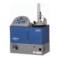
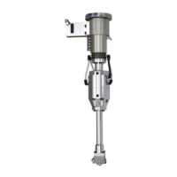
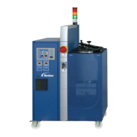
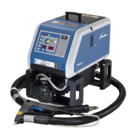
Options and Accessories
10‐3
P/N 213828_11
2014 Nordson Corporation
VersaBlue_PPA
Option in configuration
code
Box Also
available
as
accessory
Description
Level Display and Control
(Variable Measuring Points)
16
- P: Level control (Ni120) with overflow protection
D: Level control (Pt100) with overflow protection
Level sensor in tank for the analog level display and
the filling signals for a filling valve.
Automatic tank filling is performed e.g. by a bulk
melter connected to the filling valve with a hose.
Additional level sensor in tank for separate overflow
protection
Light tower 17 W: Four colors. Indicates operating mode of melter.
Main switch 18 - 1: red‐yellow, 4‐pin
2: black, 3-pin
3: black, 4-pin
X: Red/yellow, 3‐pin (standard)
Field bus communication 19 - D: PROFIBUS‐DP
N: ControlNet
E: EtherNet/IP
P: Profinet IO
Separate line speed signal
inputs
20 - K: Every motor receives its own line speed signal.
Casters 21 C: To move melter; two can be locked
Inert Gas Equipment 22 G: Used to blanket tank contents with inert gas. This
is needed when processing certain materials.
Filter cartridge / safety valve 23 C: 0.8 mm mesh size / 85 bar - only VA -
D: 0.2 mm mesh size / 100 bar - only VA -
G: 0.8 mm mesh size / 100 bar - only VA -
H: 0.1 mm mesh size / 85 bar - only VA -
X: 0.2 mm mesh size / 85 bar (standard)
 Loading...


