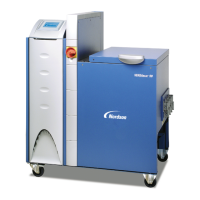
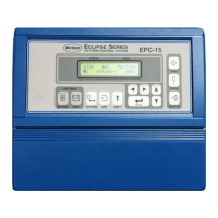
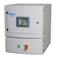
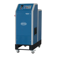
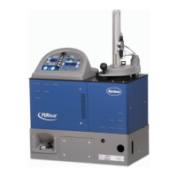
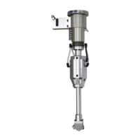
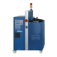
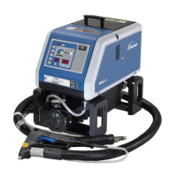
Fig. 3‐13
Proportional valve
ON
4 - 20 mA
ON
0 - 10 V
1 2345678
ON
OFF
ON
ON
ON
OFF
OFF
OFF
ON
OFF
ON
ON
ON
OFF
OFF
OFF
SW1
Installation
3‐16
P/N 213828_11
2014 Nordson Corporation
VersaBlue_PPA
Pneumatic Pressure Control / Bypass Control (contd.)
Interface Assignment XS4: Automatic Pneumatic
Pressure Control
PIN Input Function
1 -
4 - 20 mA
0 - 10 V
Proportional valve pump 1
2 +
3 -
4 - 20 mA
0 - 10 V
Proportional valve pump 2
4 +
Proportional Valve
The proportional valves for automatic pneumatic pressure control are located
in the melter tower.
DIP switch SW1 to switch between 0 - 10 V and 4 - 20 mA.
0 - 10 V
Timer Relay
The voltage supply to the proportional valves is linked to the signal System
ready. Wiring diagram page SLP 164a and SLP 71.
The timer relay -164K6 is located in the left door of the electrical cabinet.
Approx. 3 s switchon delay (timer relay P/N 7157900)
Compressed air
Proportional valve
NozzleApplicator
Hose
Pneumatic pressure
control valve
MotorPump
Filter
Tank
M
0-10 V or 4-20 mA
Fig. 3‐14 Option P: Automatic pneumatic pressure control (1 pump)
 Loading...


