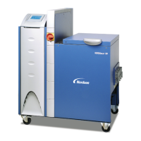
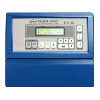
Level display
Fig. 4‐13
%
%
%
55
80
10
Filling
Stop at
Start
at
Low level
warning
Level
%10
Fig. 4‐14
V13
Fig. 4‐15
Filling valve
25 mm
25 mm
max1
max2
Fig. 4‐16
Cross‐section of tank
Operation
4‐22
P/N 213828_11
2014 Nordson Corporation
VersaBlue_PPA
Level Display and Control (Options)
Perform calibration (Refer to Replacing Evaluator in the section Repair).
As soon as the material is changed, the level parameters on the control panel
must be adapted to the new material.
Automatic Tank Filling
Automatic tank filling is performed e.g. by a bulk melter connected to the
optional filling valve with a hose. Level sensors in the tank start and stop the
filling process.
Maximum Level
The level should not exceed 25 mm (1 in.) under the rim of the tank (max1);
for melters with inert gas equipment: 25 mm (1 in.) under the inert gas inlet
hole (max2).
Adapt the maximum level to the adhesive dispensing speed. Feed adhesives
sensitive to temperature quickly to prevent loss of quality.
 Loading...


