10-24 Adjusting the rectifier and the dc distribution shelf
AccessNode 323-3001-210 Issue 1.0
Procedure 10-7 (continued)
Verifying dc distribution shelf alarms
Action
Step Action
1 Ensure that all of the circuit breakers on the BIP are turned to the OFF
position.
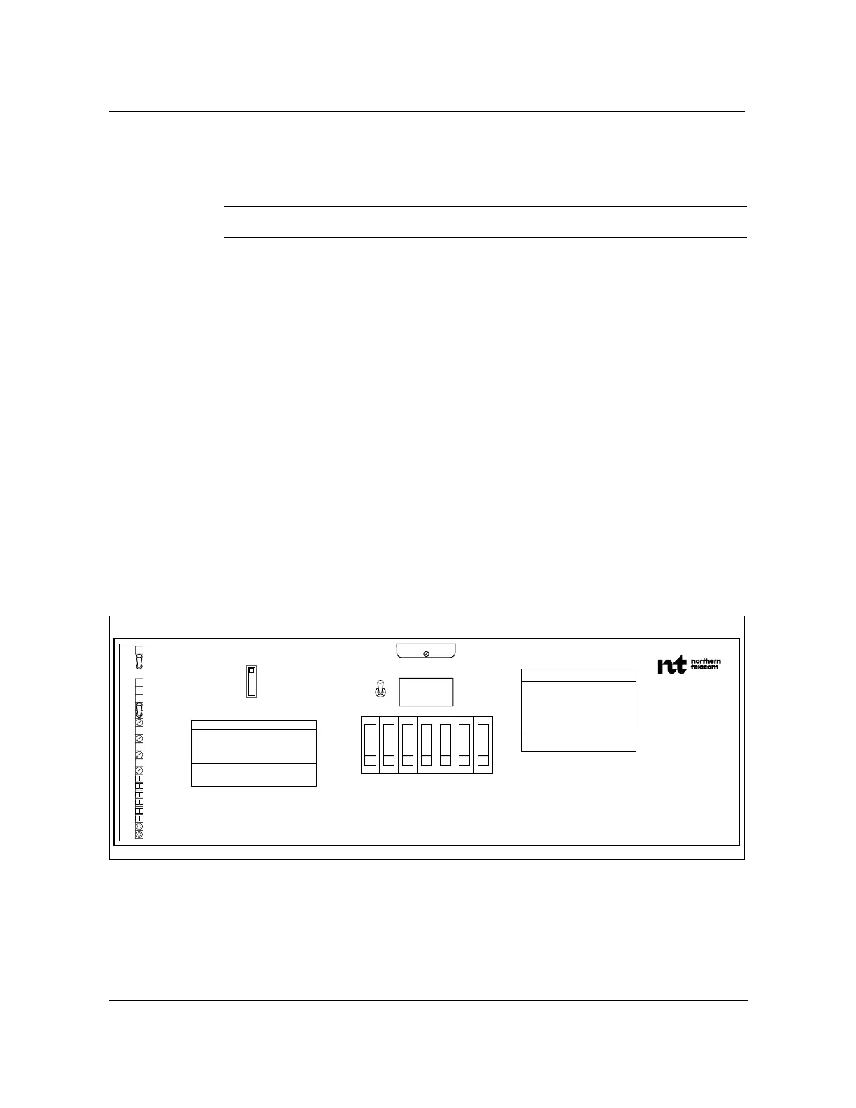
2 Turn all circuit breakers on the dc distribution shelf to the ON position (see
Figure 10-5 on page 10-24).
3 Record the voltage displayed on the faceplate readout.
4 Confirm that the FA alarm indicator is extinguished.
5 Turn OFF CB1 on the dc distribution shelf to verify that the FA alarm LED
illuminates red.
6 Turn CB1 back ON to verify that the FA alarm LED extinguishes.
7 Turn OFF, then ON, each of the circuit breakers, one at a time, to verify that
the FA indicator illuminates and extinguishes with each breaker trip.
8 Turn all breakers back to the OFF position.
9 Turn ON the EQL switch on the dc distribution shelf to verify that the EQL
indicator illuminates yellow and that the voltage level displayed on the
faceplate display corresponds to the EQL level (-55.5 ± 0.1) set on the
rectifiers.
Figure 10-5
NT6C14JC DC distribution shelf faceplate
FW-11100
—continued—
FW-11100
CB1 2 3 4 5 6 CB7
EQL
OFF
EQL
ON
RFA MAJ
RFA MIN
FA
NORM
BYP
LVD ADJ
LVD ALM
TST ADJ
TST BYP
LVDR
LV ALM
1
SEN
6
BAT GRD
-48V
CAUTION/ATTENTION
INTENDED FOR INSTALLATION IN
LOCATION ACCESSIBLE ONLY TO
QUALIFIED PERSONS.
HAZARDOUS VOLTAGES INSIDE.
TO BE HANDLED BY A QUALIFIED
PERSON ONLY.
CAUTION/ATTENTION
FOR CONTINUED PROTECTION AGAINST
RISK OF FIRE REPLACE ONLY WITH
SAME TYPE AND RATING OF FUSE.
POUR EVITER TOUT RISQUE D'INCENDIE
REMPLACER LES FUSIBLES PAR DES
FUSIBLES DU MEME TYPE ET CALIBRE
SENSE
1-1/3A
MBP DIST
NT6C14JA
REL-XXX
SER-XXX
VOLTS
AMPS
VOLTS/AMPS
LV ADJ