13-16 Cabinet and equipment wiring and cabling
AccessNode 323-3001-210 Issue 1.0
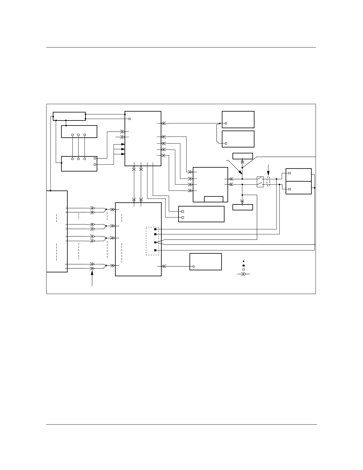
DC power distribution
This section details the dc power distribution throughout the S800A.
Figure 13-9 shows the dc power distribution diagram.
Figure 13-9
DC power distribution diagram
FW-15248
Bat. Rtn. CU A
AC panel
Rectifier
shelf
FG Bar
AC
PWR
cables
FG
1
SPG
Bat 1
Bat 2
AB
Batt 1
Batt 2
Batt 3
Batt 4
Pin Field
Roof
fan units
Group 1
Roof
Fan units
Group 2
H/W TS
RPTR 1
10A
RPTR 1
PWR
RPTR 2
PWR
DSX
PWR
10A
RPTR 2
BIP
DC shelf
NT1W87BB
NT1W87BA
NT4K84YB
NT1W84DA
NT1W84DB
CU A
CU B
NT7A6980/82
NT1W87AB
NT1W64AA
NT1W64AA
NT1W64AA
NT1W64AA
NT1W64BA
NT1W64BA
NT1W64BA
NT1W64BA
NT1W64CA
NT1W64CA
NT1W64CA
NT1W64CA
B1
RECT 1
RECT 2
A1
A4
B4
B2
Legend:
- Wire-wrap pin
- Terminal block connector
- Plug-in connector
.
- Internal cable joint
FAN
BK
Bat. Rtn. CU B BK
Fan alarm (shelf fans) SL
Fan alarm (shelf fans) SL
Fan alarm (roof fans) BL
11
12
(-48 RTN)
30 amp outputs
BIP
NT1W87DA
Battery
breaker
panel
Strg 1
Strg 2
Strg 7
Strg 8
Strg 9
Strg 10
Strg 13
Strg 14
Battery
racks
NT4K84YB
Battery interface connector field
FW-15248
9
7
Fan shelf 2
Fan shelf 1
Bat 3
Bat 4
AC Compartment
Terminal
block
(TB 13)
2
3