Cabinet and equipment wiring and cabling 13-51
AccessNode Series 800A Outside Plant Cabinet Installation 323-3001-210 Issue 1.0
DS1 I/O card wiring
DS1 I/O wiring tables are listed in the next section for DSX to repeater wiring
(see Table 13-12 on page 13-54 through Table 13-15 on page 13-60).
DS1 I/O input cards connect to connectors J30, J31, J34, J35, J38, J39, J42 and
J43 on the ABM backplane (see Figure 13-37 on page 13-52).
DS1 I/O output cards connect to connectors J32, J33, J36, J37, J40, J41, J44
and J45 on the ABM backplane (see Figure 13-37 on page 13-52).
DSX and repeater cabling
The DSX panel, when installed, interfaces the DS1 I/O cards of the ABM shelf
to the repeater shelf. Reference Figure 13-36 on page 13-50 for the block
diagram of the DS1 I/O to DSX to repeater cabling.
DSX wiring tables
Table 13-12 on page 13-54, Table 13-13 on page 13-56, Table 13-14 on page
13-58, and Table 13-15 on page 13-60 show the wiring connections from the
DS1 I/O cards to the DSX panel to the repeater shelf.
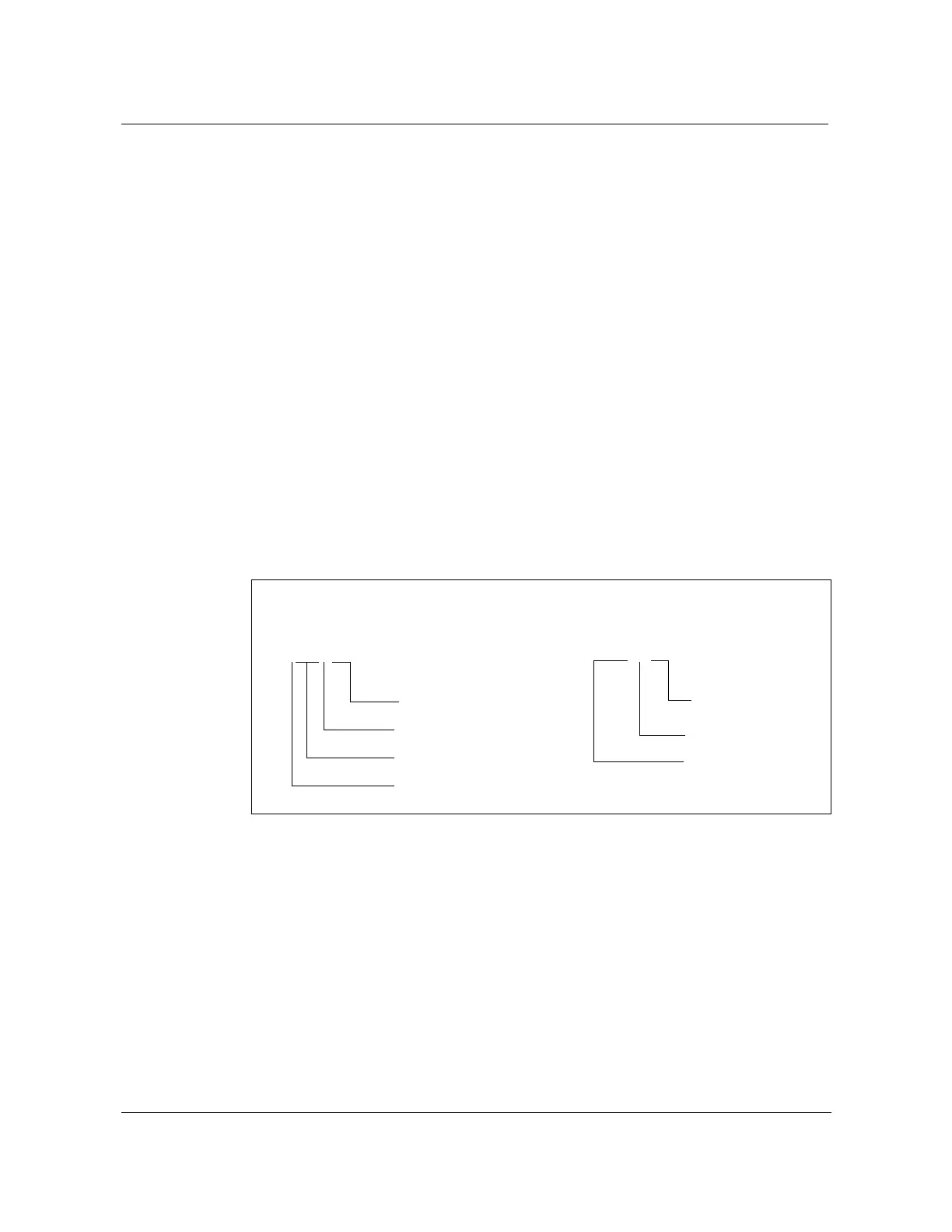
The signal names listed in the tables are defined in the following chart:
A IN T 01
Pin Number
(T)ip or (R)ing
IN or OUT
Group A or Group B
DSX REPEATER
OUT T 01
Pin Number
(T)ip or (R)ing
DSX IN or OUT
Connector