13-22 Cabinet and equipment wiring and cabling
AccessNode 323-3001-210 Issue 1.0
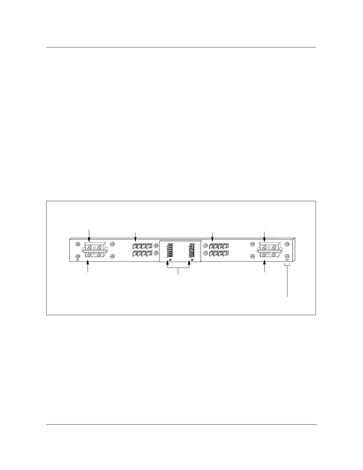
Battery breaker panel dc power connections
The BBP is connected to the dc distribution shelf (see Figure 13-13 on page
13-21 and Figure 13-9 on page 13-16) through the BBP power terminals
located at the rear of the unit (see Figure 13-14 below).
The back-up battery supply is channeled through the breaker interface
connectors located in the rear left swing frame (see Figure 13-16 on page
13-25) to the BBP to the battery breakers (A1 through A4 and B2 through B4).
When the second repeater option is installed, the repeater 2 shelf is powered
from the BBP through circuit breaker B1.
In addition to the dc powering, the BBP is the alarm monitoring connection
points for the fan fail alarm circuit (see Figure 13-26 on page 13-38) and the
dc power failure circuits for the CU A and CU B dc power outputs of the
battery interface panel (see Figure 13-18 on page 13-28).
Figure 13-14
BBP rear view
FW-15247
POS GND
NEG
1
NEG 48V
POS RTN
234
NC
C
ND
NC
C
NO
ALARM
PWR
NC
C
ND
NC
C
NO
ALARM
FAN
B A
Chassis
GND ( Typical 2 places )
Wirewrap pin arrangement
for external alarm hookups
Output
terminal
block B
Upper terminals
negative power input
(To DC distribution shelf,
Batt 2-48V)
POS GND
NEG
1
NEG 48V
POS RTN
234
Lower terminals
positive power input
(To DC distribution shelf,
Batt 2-48V)
Output
terminal
block A
Upper terminals
negative power input
(To DC distribution shelf,
Batt 1-48V)
Lower terminals
positive power input
(To DC distribution shelf,
Batt 1-48V)
REAR VIEW
1
6
7
9
12
1
6
7
12
FW-15247