13-12 Cabinet and equipment wiring and cabling
AccessNode 323-3001-210 Issue 1.0
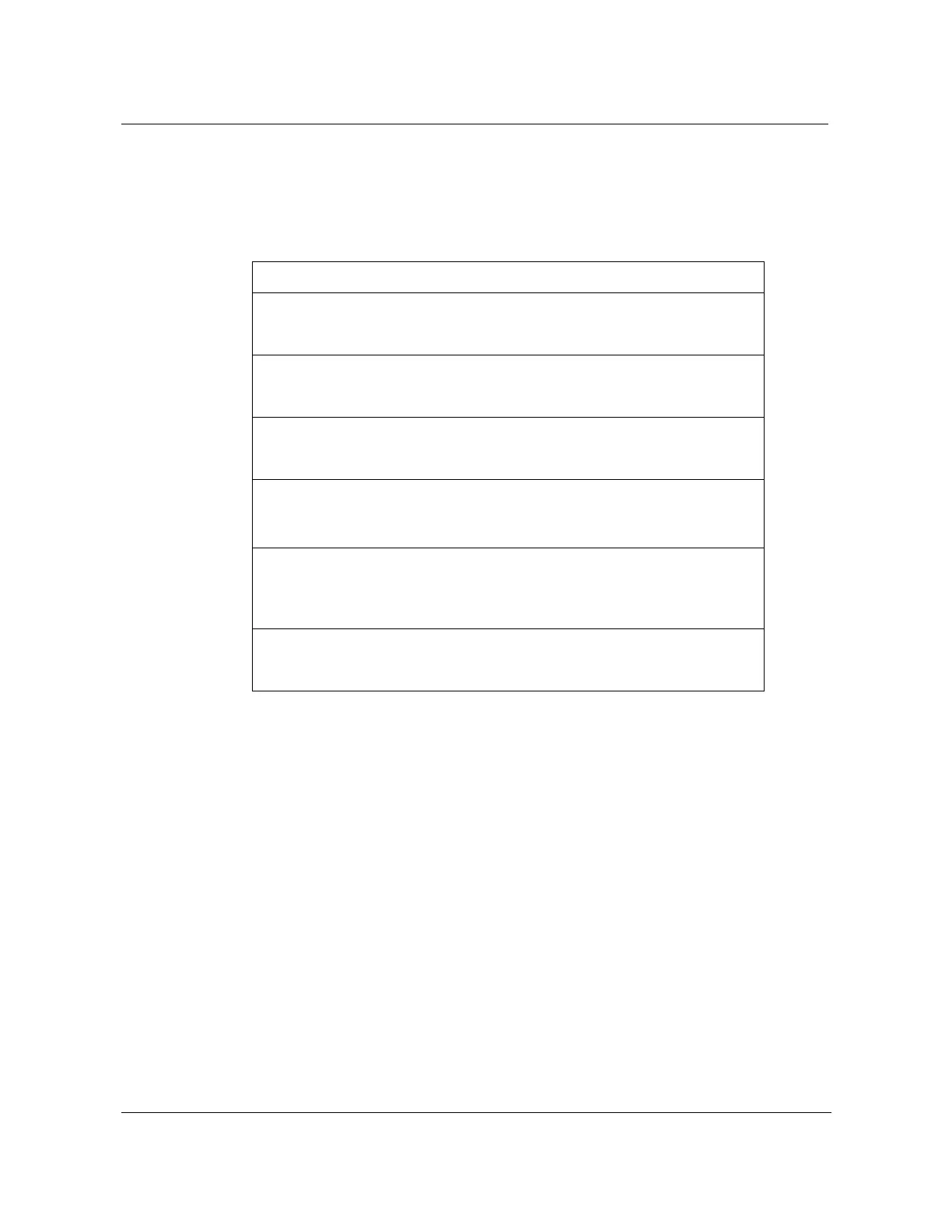
Table 13-3 shows the circuit breaker designations and the lead connections for
the NT7A68AA-CA and NT7A68DA-FA power pedestal options (see
Figure 13-6 on page 13-13 and Figure 13-7 on page 13-14).
Note: CB #3, positions 7-8 are not wired to the cabinet outlet box for non
N+1 applications.
Table 13-3
NT7A68AA-CA power pedestal circuit breaker designations and connections
L1 L2 Description Designation Color Position
100
Main breaker MAIN
BK 1
100 BK 2
20
Rectifier 1 CB #1
BK 3
20 RED 4
20
Rectifier 2 CB #2
BK 5
20 RED 6
20
Rectifier 3
(
Note
)
CB #3
BK 7
20 RED 8
15 Heaters CB #4 BK 9
10 Internal
GFCI
CB #5 BK 10
15 External GFCI CB #6 BK 11
Blank 12