13-14 Cabinet and equipment wiring and cabling
AccessNode 323-3001-210 Issue 1.0
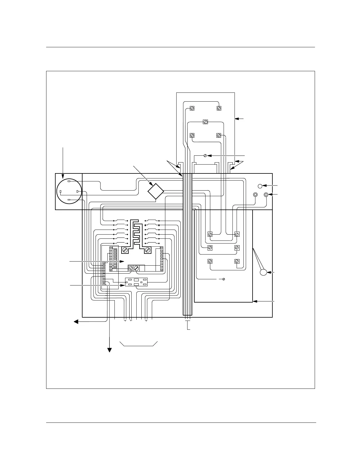
Figure 13-7
100/100 amp ac power pedestal (NT7A68DA-FA option)
FW-15170
G
W
G
Line
Load
Emerg
GRN
RED
WHT
BLK
L1
L2
Line
Load
B
B
G
B
B
W
B
B
W
To outlet box
To
GND rod
To GND
To neytral
To rect #1
To rect #2
To rect #3
To heaters
To non-GFI
B
B
B
R
B
R
B
R
B
B
B
W
W
1
2
3
4
5
6
100A
7
8
9
10
11
12
B
B
Y
W
G
R
B
L1
L2
100A
20A
20A
20A
15A
10A
15A
Blank
Neutral
Load center
DPDT safety
knife switch
Ground
Notes:
1) CB3; Positions 7-8 are not wired to cabinet
outlet box for non N+1 applications.
2) Meter socket and right mounting nipple provided
by local electrical contrator or power company.
GND nipple to
base GND
connection
Power meter
socket base
(Up to 15 x 24)
250V
primary
power
indicator
light
Handle (Ref)
Warning:
This main
does not
disconnect
power from
the secondary
surge protector,
indicator light,
or the 1A fuses.
DPDT
safety
transfer
switch
100A, 240V,
NEMA1
Incoming line power
accommodates power company buried cable
2-1/2" PVC
conduit entrance
Secondary
surge protector
Emergency
connector
receptacle
hubble
pin & sleeve or
equiv
100A, 240V
Load
center
frame
200A,
240V
AC
compartment
15A, 110V,
GFI outlet
To
cabinet
GND bar
positions
#1 & 8
Fuse
holders
1A
Nipple base
(Customer
provided)
FW-15170
Neutral