The baud rate generator is activated only when the SPI is in the master mode and a serial
transfer is taking place. In the other cases, the divider is disabled to decrease I
DD
current.
The baud rate divisor equation is as follows (except those reserved combinations in the
SPI Baud Rate Divisor table).
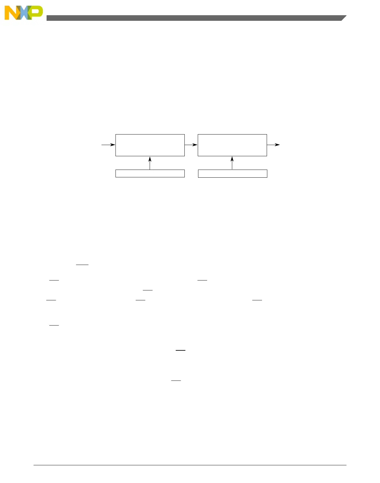
BaudRateDivisor = (SPPR + 1) × 2
(SPR + 1)
The baud rate can be calculated with the following equation:
BaudRate = BusClock / BaudRateDivisor
MASTER
SPI
BIT RATE
BAUD RATE DIVIDER
PRESCALER
BUS
CLOCK
SPPR2:SPPR1:SPPR0
SPR3:SPR2:SPR1:SPR0
DIVIDE BY
1, 2, 3, 4, 5, 6, 7, or 8
DIVIDE BY
2, 4, 8, 16, 32, 64, 128,
256, or 512
Figure 37-25. SPI Baud Rate Generation
37.4.7 Special Features
The following section shows the module special features.
37.4.7.1 SS Output
The SS output feature automatically drives the SS pin low during transmission to select
external devices and drives the SS pin high during idle to deselect external devices. When
the SS output is selected, the SS output pin is connected to the SS input pin of the
external device.
The SS output is available only in master mode during normal SPI operation by asserting
the SSOE and MODFEN bits as shown in the description of the C1[SSOE] bit.
The mode fault feature is disabled while
SS output is enabled.
Note
Be careful when using the
SS output feature in a multimaster
system because the mode fault feature is not available for
detecting system errors between masters.
Chapter 37 Serial Peripheral Interface (SPI)
KL25 Sub-Family Reference Manual, Rev. 3, September 2012
Freescale Semiconductor, Inc. 677
 Loading...


