24V
5V
5VS0 5VS
CE1
ASIC
Power
supply
control CPU
AC→24V
Main power
switch
AC→5V
Sub power supply
Main power supply
24V→5V
Heater
circuit
Power switch
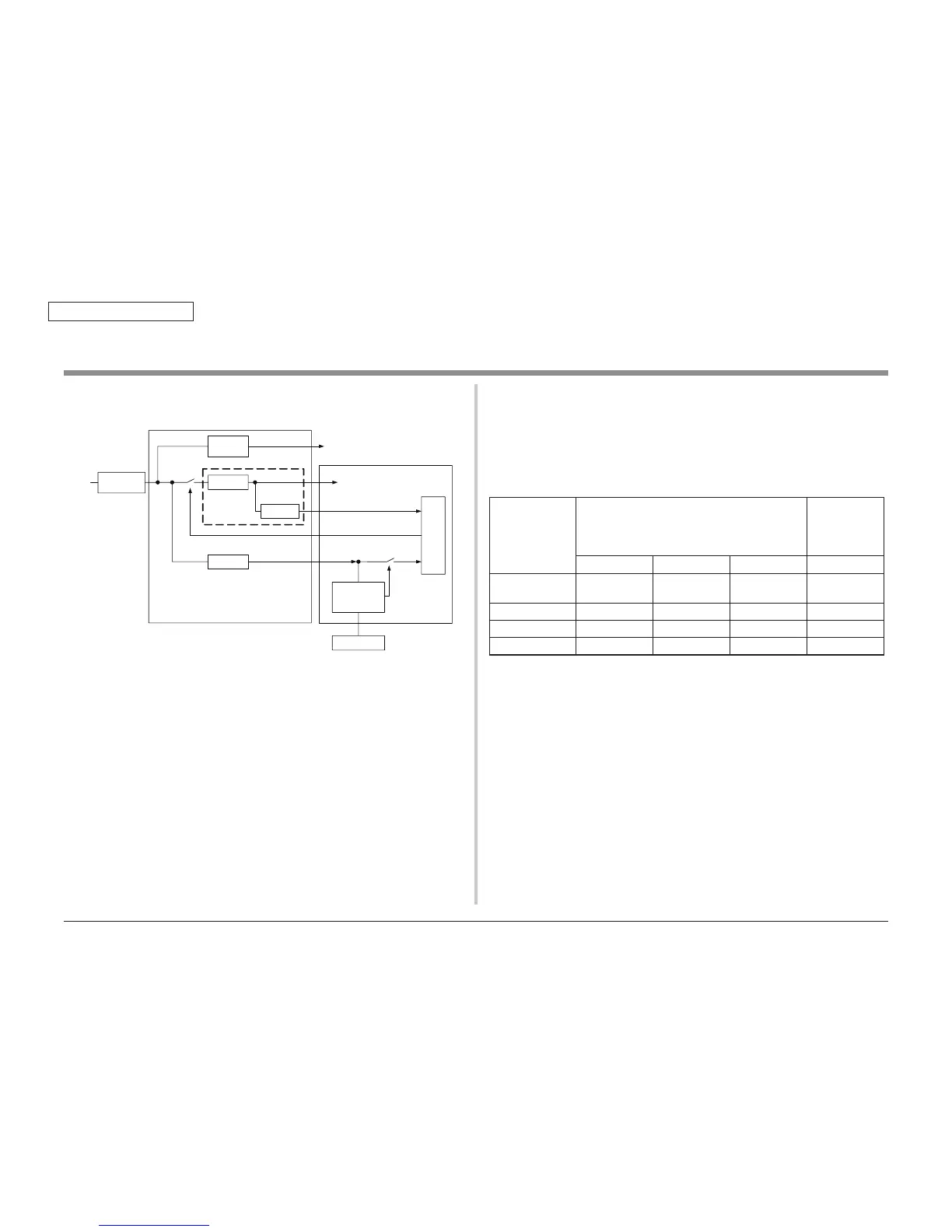
The low-voltage power supply has two kinds of power supply, which is main power supply (5V,
24V) and sub power supply (5VS0).
The main power supply (24V, 5V) is turned on and off by CE1 ASIC of the PU/CU board.
The sub-power supply (5VS0) is turned on when plugging the AC cable into the socket and
turning on the Main power switch.
Therefore, the maintenance operations should be performed after turning off the Main power
switch, unplugging the AC cable and checking the LED on the PU/CU board lighted off.
Tu r ni n g ON an d O F F o f 5 VS t o t he ma in CP U i s p er fo r m e d b y t he Po w er su p pl y c o nt ro l C PU.
2.3.2 Power-supply Voltage in Each Mode
The output voltage value of the low-voltage power supply is different in each operation mode
as shown in the following table.
When measuring the output voltage value of the low-voltage power supply, the judgment of
validity should be performed based on the following table.
Operation mode
Output voltage value of the low-voltage power supply
Power-supply
voltage value
in the PU/CU
board
24V line 5V line 5VS0 line 5VS line
In operation, and
Standby
24V 5V 5V 5V
Power save 24V 5V 5V 5V
Sleep OFF OFF 5V 5V
OFF OFF OFF 5V OFF
2.3.3 Thermistor for Temperature Alarm
The low-voltage power supply mounts the thermistor for temperature alarm.
When the temperature of the low-voltage power supply is abnormal, Service Call SC SC166-
01, 02, 03 is displayed.
For details and handling methods of each service call, refer to 'Service Call Error List' in the
section 4 Troubleshooting Procedure.