45530603TH Rev.2
6-19
Oki Data CONFIDENTIAL
6. REPLACEMENT OF PARTS
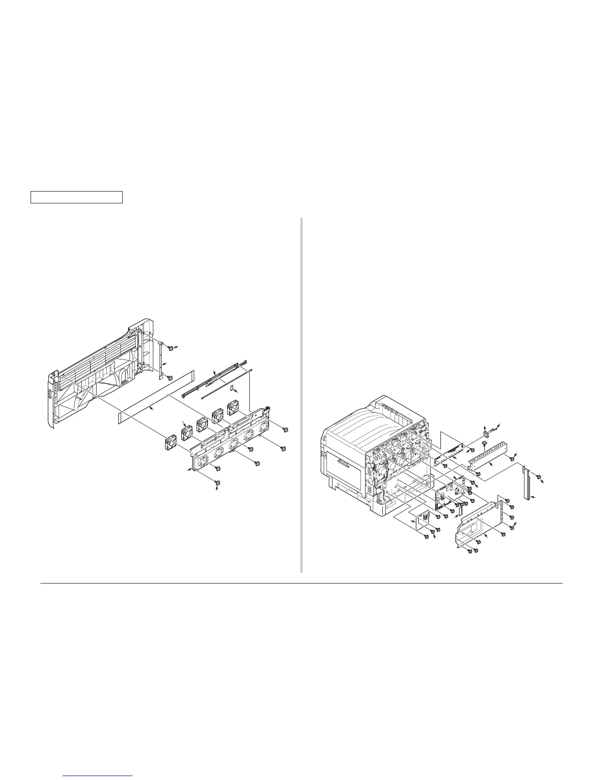
6.2.19 Filter-Front / Motor-FAN / Board-F1E(External
LED PCB)
(1) Remove the Cover-Assy-Front.(Refer to section 6.2.18)
(2) Remove the two screws(black)(8mm)
①
and remove the Cover-cable
②
.
(3) Remove the six screws(black)(8mm)
③
and remove the Duct-Assy
④
.
(4) Remove the Filter-Front
⑤
.
(5) Remove the Motor-FAN
⑥
.
(6) Remove the Cover-Lends
⑦
and remove the Board-F1E
⑧
.
6.2.20 Board-F1D(Driver relay PCB) / Board-F1Y(PU/
CU PCB) / Board-F1X(Spot color PCB) / Board-
Memory / FAN
(1) Remove the Cover-Rear.(Refer to section 6.2.11)
(2) Lossen the eight screws(silver)(6mm)
①
and slide the Plate-Cover-MainPCB
②
for
MPT side and remove it.
(3) Remove the three screws(silver)(6mm)
③
and remove the Plate-Shield-F1D
④
.
(4) Remove the three screws(silver)(6mm)
⑤
and remove the Plate-Cover-FFC
⑥
.
(5) Disconnect the all cables from board.
(6) Remove the four screws(silver)(6mm)
⑦
and remove the Board-F1X
⑧
.
( for C941 only)
(7) Remove the nine screws(silver)(6mm)
⑨
and remove the Board-F1Y
⑩
.
(8) Remove the two screws(silver)(6mm)
⑪
and remove the Board-F1D
⑫
.
(9) Remove the Board-Memory
⑬
from the Board-F1Y
⑩
.
(10) Remove the two screws(silver)(20mm)
⑭
and remove the FAN
⑮
.

 Loading...