45530603TH Rev.2
2-19
Oki Data CONFIDENTIAL
2. DESCRIPTION OF OPERATION
2.5 Initialization processing
Description
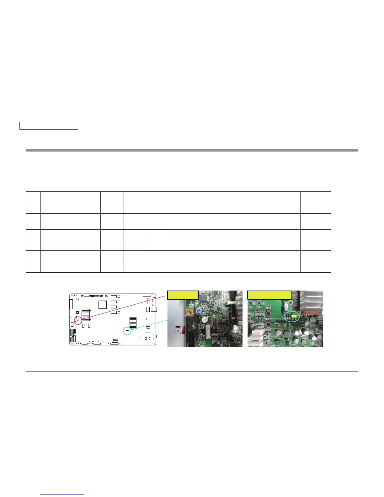
· The state of initialization is indicated by LED (Power Supply LED, initialization LED 1, 2, 3).
· The Power Supply LED is blinking in first step. In the case of the Power Supply is abnormaly, the LED is blinking at high speed.
· The initialization is start with turning on the Main Power Supply by turning on the Power Supply Switch in state of turning on of the Main Power Supply Switch.
Ta bl e o f t he b lin ki ng pa tt er n o f t he LED in i ni ti ali z at io n
Step Initialization processing LED1 LED2 LED3 Motion of Circuit Display of OP
panel
1 Boot start
■ ■ ■
Reading the boot program Display of OKI-
logo
2 Completion of RAM Chack for boot
□ ■ ■
Expansion of the boot program after RAM check for boot.
3 Completion of the recognition for
NAND-Flash
■ □ ■
Recognition processing of NAND-Flash
(
IC702
)
4 Completion of the Main CE1
□ □ ■
Recognition processing of CE1(MAIN
)
5 Completion of the Sub CE1
■ ■ □
Recognition processing of CE1(SUB)
6 Completion of loading the PU-FW
□ ■ □
The Engine control program is read from NAND-FLAHS
(
IC702) and
expanded to memory.
7 Completion of loading the CU-FW
Completion of the board initialization
■ □ □
The CU control program is read from NAND-FLAHS(IC702) and
expanded to memory.
Initialinzing
8 Completion of the apparatus
initialization
■ □ □
Ready to Print
■
lighting
□
Extinction
GDDC
FINISHER
PUFAN
CUFAN
HEATIF
HVOLT
DUP
DCHEAT
DCBELT
RAILIF
FPD
R8C/
34C
HEAD1_M0
HEAD2_M1
HEAD3_M2
HEAD4_M3
SATAIF
XIF
SATAPOW
DDR3
DDR3
DIMM
F1Yᇶᯈ
MPTCOV
FDMRG2CL
HOPM
TRY
REG1CL
HOP
CL
R8C/
33d
Y
M
C
K
EMAIN
DDR3
DDR3
POWER
RCOVER
POWFAN
WTNR
COLSNS
THICK
PSZ
TR2SNS
TRYSNS
MPTIF
Batt
ery
Trans
ENV
DRIVE0
RFID
CPU
MAIN
LAN
USB
IC702
䠄NAND FLASH䠅
POWLED
LED1
LED2
LED3
INITMODE
IC6
IC31
Power Supply LED
Initialization LED1, 2, 3
When problem occur
It's possible Memory error, in case extinction the LED 1,2,3 or blink the LED2,3 when power switch turn on. Change the Memory DIMM and check retrieve.
In case LED1,2,3 stop at Step1 to 6, trouble occur the board. Change the Main board.