DMTA-20015-01EN [U8778402], Rev. J, January 2014
OMNI-M2-PA1664/16128/32128/32128PR Module Specifications
185
Appendix N: OMNI-M2-PA1664/16128/32128/32128PR
Module Specifications
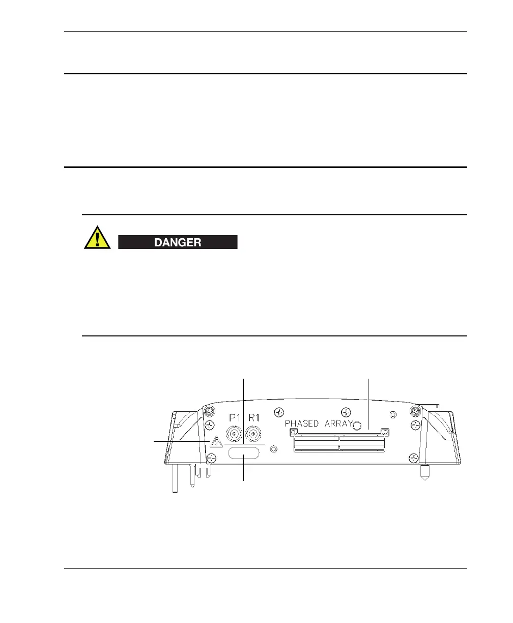
• To reduce the risk of electric shock, avoid touching the inner conductor of the
LEMO connectors. Up to 340 V can be present on the inner conductor of the UT
connectors, and up to 115 V can be present on the PA connector. The warning
symbol near the LEMO connectors signals this electric shock risk (see Figure N-1
on page 185).
• Reinforced insulation must be provided for the probes connected to the module.
Figure N-1 Module side view
Warning symbol
Phased array connectorUT connectors
Module configuration
label