DMTA-20015-01EN [U8778402], Rev. J, January 2014
List of Figures
199
List of Figures
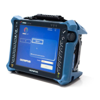
Figure i-1 The OmniScan MX2 ............................................................................................. 1
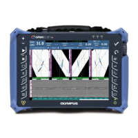
Figure i-2 The OmniScan MX ............................................................................................... 2
Figure i-3 Module identification label ................................................................................ 2
Figure i-4 The OmniScan MX2 membrane vent ................................................................ 6
Figure 1-1 Front panel of the OmniScan MX2 .................................................................. 22
Figure 1-2 Right side panel of the OmniScan MX2 ......................................................... 26
Figure 1-3 Left side panel of the OmniScan MX2 ............................................................ 27
Figure 1-4 Top panel of the OmniScan MX2 ..................................................................... 28
Figure 2-1 The Shut Down button ...................................................................................... 32
Figure 2-2 Saving the setup ................................................................................................. 32
Figure 2-3 Sleep mode selection ......................................................................................... 33
Figure 2-4 The OmniScan MX2 DC power adaptor plug ............................................... 35
Figure 2-5 Battery charge status: Charge remaining in both batteries ......................... 36
Figure 2-6 Removing a lithium-ion battery ...................................................................... 38
Figure 2-7 Attaching a ferrite clamp filter to a cable (example shown with
the scanner interface cable) .............................................................................. 43
Figure 2-8 OmniScan MX2 connection diagram — ferrite clamp filters ...................... 44
Figure 3-1 Module with PA connector cap ....................................................................... 49
Figure 6-1 The serial connector .......................................................................................... 62
Figure 6-2 The scanner interface LEMO connector (contact view) ............................... 63
Figure 6-3 The scanner interface adaptor LEMO connector (solder-cup view) .......... 66
Figure 6-4 The scanner interface adaptor DE-15 connector (solder-cup view) ........... 67
Figure 6-5 The alarm and I/O connector ........................................................................... 68
Figure 7-1 Front panel of the OmniScan MX .................................................................... 76
Figure 7-2 Information provided on each key ................................................................. 78
Figure 7-3 Right side panel of the OmniScan MX ........................................................... 83
Figure 7-4 Left side panel of the OmniScan MX .............................................................. 84
Figure 7-5 Top panel of the OmniScan MX ....................................................................... 85
Figure 8-1 The OmniScan MX DC power adaptor plug ................................................. 89
Figure 8-2 Battery charge status: Charge remaining in both batteries ......................... 90