DMTA-20015-01EN [U8778402], Rev. J, January 2014
Chapter 2
44
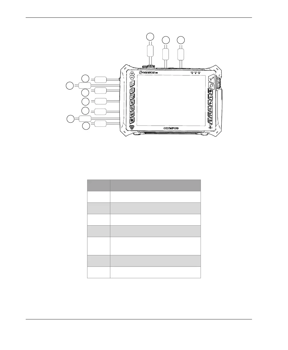
Figure 2-8 OmniScan MX2 connection diagram — ferrite clamp filters
Table 8 Ferrite clamp filter locations
ID Description
1 Scanner connection
2 Alarm and I/O connector
3SVGA output
4 Serial port
5 Probe connection (depending on
the module)
6 LAN connection
7 USB device connections