DMTA-20015-01EN [U8778402], Rev. J, January 2014
Chapter 6
64
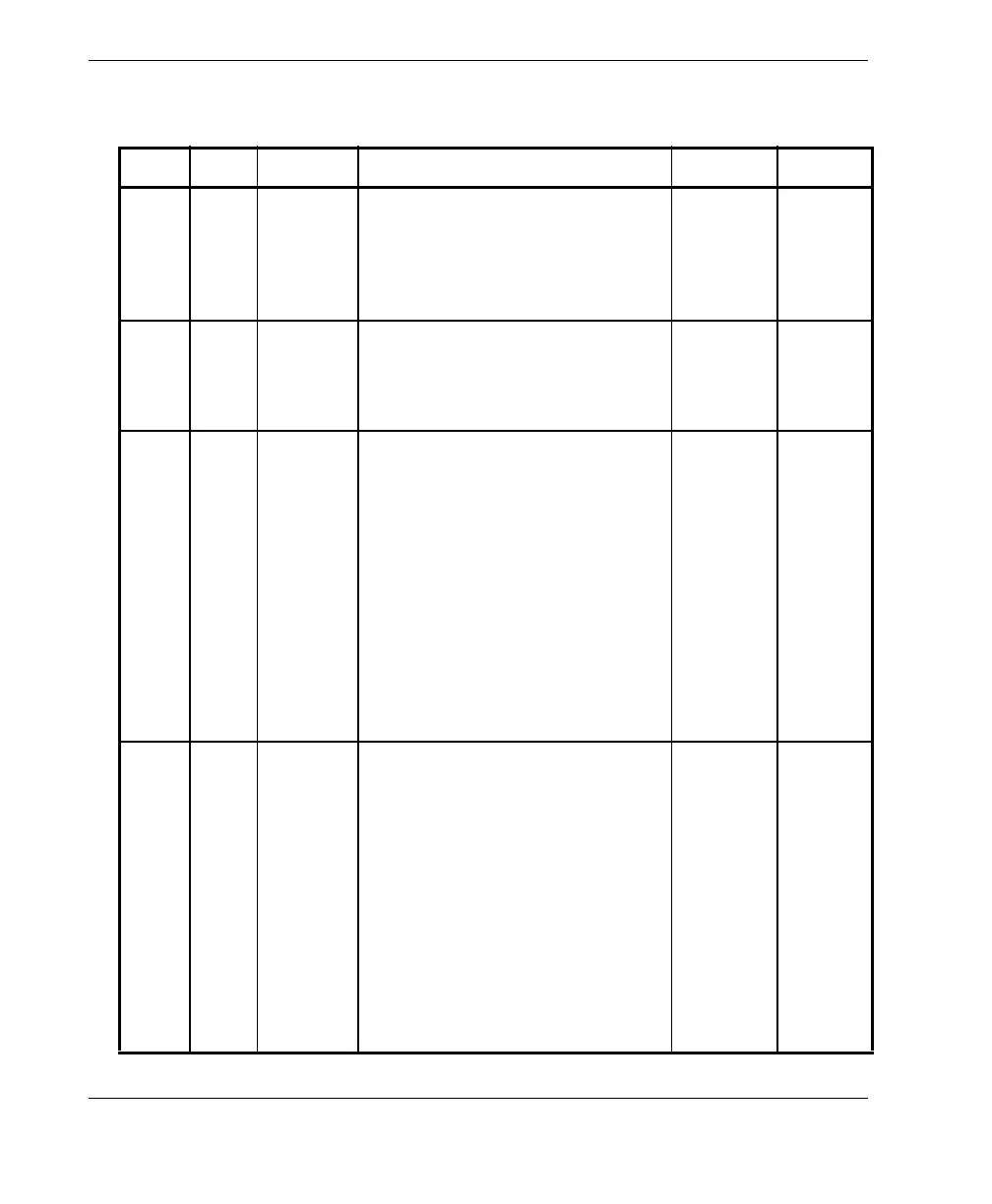
Table 13 Pinout for the scanner interface LEMO connector
Pin I/O Signal Description Current Level
1InAINAnalog input ±2.5mA
(2 kΩ
input
impedan
ce)
±5 V
2 Out +5 V External power supply
This power is shared with pin 2
of the serial connector (see
section 6.1 on page 62).
500 mA N/A
3InDIN1/
Preset1
Digital input 1/preset axis 1
Programmable input. Can be
configured as generic input 1, or
as the preset of encoder 1. Refer
to the OmniScan MXU Software
User’s Manual (“Configuring the
Digital Input” section) for
information on programming
this input.
To preset, you must use a high-
level signal with a minimum
signal length of 50 ms.
N/A TTL
4InDIN2/
Preset2
Digital input 2/preset axis 2
Programmable input. Can be
configured as generic input 2, or
as the preset of encoder 2. Refer
to the OmniScan MXU Software
User’s Manual (“Configuring the
Digital Input” section) for
information on programming
this input.
To preset, you must use a high-
level signal with a minimum
signal length of 50 ms.
N/A TTL