CT Analyzer User Manual
156 OMICRON
The following values are displayed in the Results CT Ratio card:
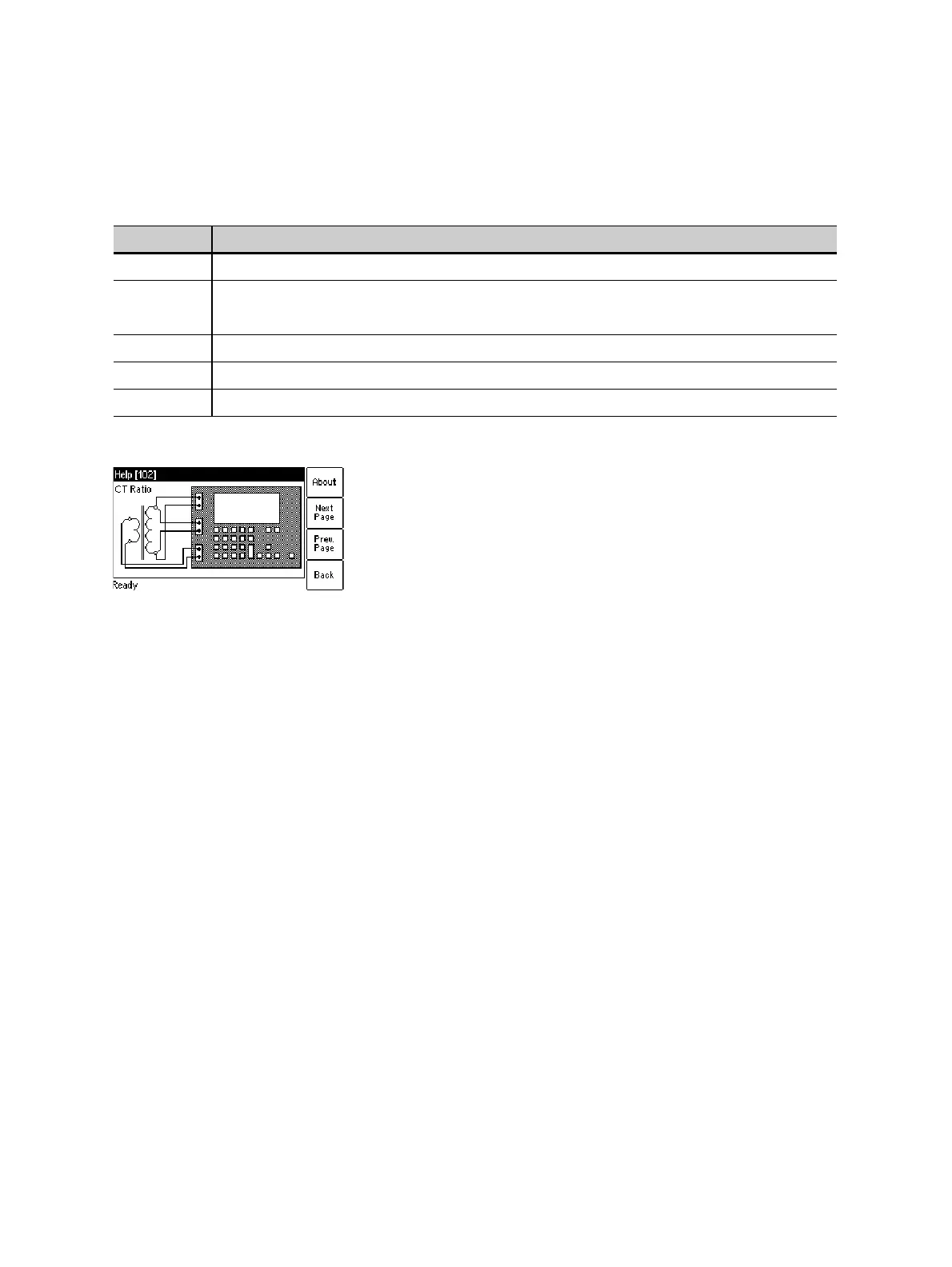
Use the following wiring for CT ratio measurement (example):
Figure 10-10: Wiring example for CT ratio measurement
Table 10-8: Values displayed for CT Ratio measurement type
Value Description
OUTPUT Internally measured RMS current value and phase of the output signal.
SEC RMS value of the voltage measured at input SEC.
This input is considered as the phase reference, therefore the phase is always 0.
PRIM RMS value and phase of the voltage measured at input PRIM.
N Current ratio of the CT calculated from the voltages measured at inputs SEC and PRIM.
f Frequency measured at input SEC.