OMICRON 161
Using the Quick Test feature
The following values are displayed in the Results Resistance card:
Note: The resistance measurement uses the serial equivalent circuit diagram for results calculation.
Use the following wiring for resistance measurement (example):
Figure 10-16: Wiring example for resistance measurement
Proceed as follows to perform a winding resistance measurement:
1. Connect the OUTPUT sockets and input SEC of CT Analyzer to the winding to be measured (see
Figure 10-16).
2. Open the Quick Test measurement function of CT Analyzer or start the CT Analyzer Quick Test tool
of the CT Analyzer Suite software.
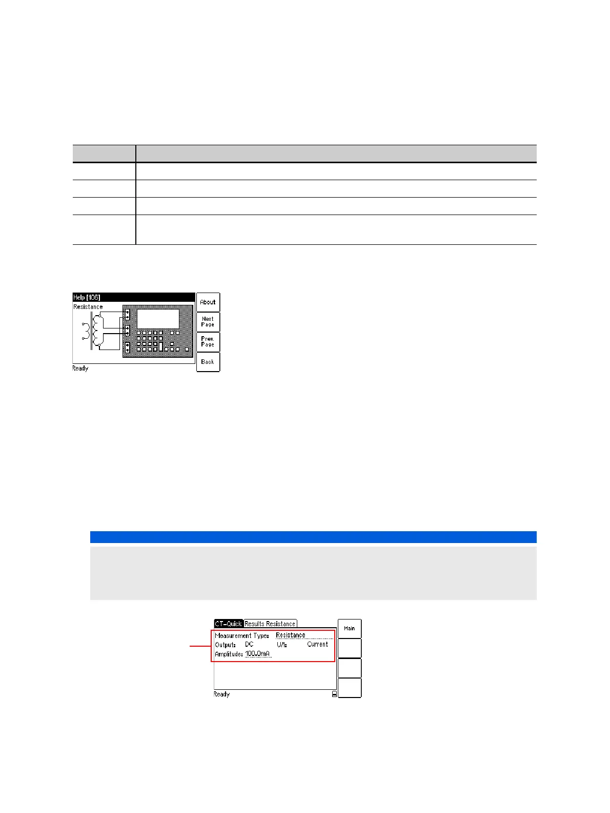
3. Select the Resistance measurement type and set the amplitude of the DC output current
appropriately. Refer to Figure 10-17.
Figure 10-17: CT-Quick test card with settings for resistance measurement
Table 10-12: Values displayed for Resistance measurement type
Value Description
OUTPUT Internally measured output current.
SEC Voltage measured at input SEC.
PRIM Not used for resistance measurement.
Rs Serial resistance, calculated from the output current and the voltage measured at input
SEC.
NOTICE
Equipment damage possible
Too high currents could destroy the winding.
► Use only low currents of e.g. 100 mA when measuring the primary side of VTs.