EasyManuals Logo

Omron CP1E Series User Manual

Omron CP1E Series
260 pages
To Next Page IconTo Next Page
To Previous Page IconTo Previous Page
Page #109 background imageLoading...
Page #109 background image
5-3
5 Installation and Wiring
CP1E CPU Unit Hardware User’s Manual(W479)
5-1 Fail-safe Circuits
5
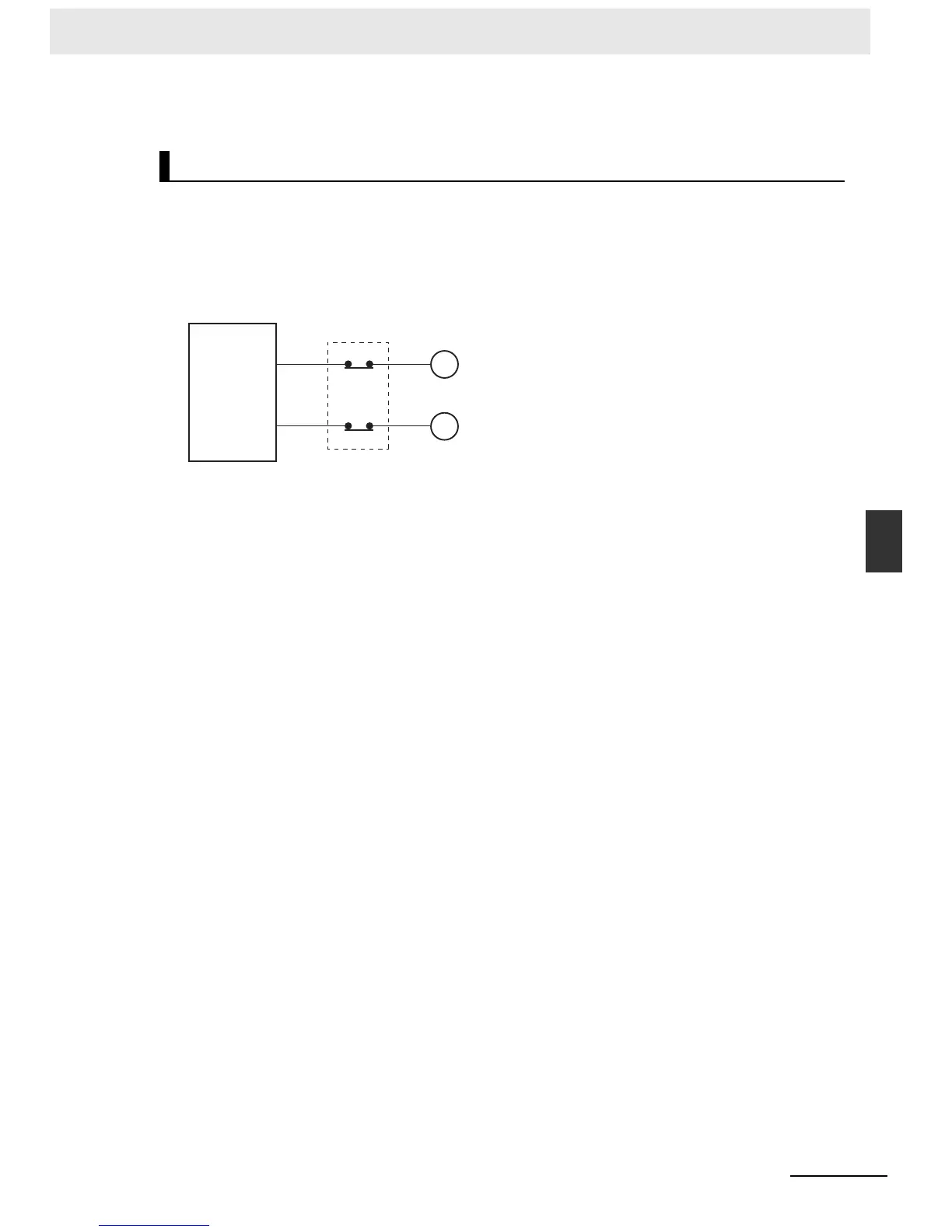
When the PLC controls operation such as the clockwise and counterclockwise operation of a motor and
if there is any possibility of an accident or mechanical damage due to faulty PLC operation, provide an
external interlock such as the one shown below to prevent both the forward and reverse outputs from
turning ON at the same time.
Example:
External Interlock Circuits
A circuit like the one shown in the dia-
gram on the left is required to prevent
outputs MC1 and MC2 from both being
ON at the same time even if both PLC
outputs CIO 100.00 and CIO 100.01
are both ON.
CP1E
Interlock Circuits
MC2
100.00
MC1
100.01
MC1
MC2
Motor
clockwise
operation
Motor
counterclock
wise operation

Table of Contents

Questions and Answers:

Question and Answer IconNeed help?

Do you have a question about the Omron CP1E Series and is the answer not in the manual?

Omron CP1E Series Specifications

General IconGeneral
Data Memory8K words
Pulse Output100 kHz for 2 axes
Communication PortsRS-232C, USB
MountingDIN rail mounting
Analog InputsOptional (via expansion units)
Analog OutputsOptional (via expansion units)
Expansion UnitsDigital I/O, Analog I/O, Temperature Sensor Units
Power Supply100 to 240 VAC or 24 VDC
CPU TypeVarious (E, N, and NA types)

Related product manuals