9 Using Expansion Units and Expansion I/O Units
9-52
CP1E CPU Unit Hardware User’s Manual(W479)
9-5-3 Specifications
Model CP1W-SRT21
Master/slave CompoBus/S Slave
Number of I/O points 8 input points, 8 output points
Number of words allocated in
CPU Unit I/O memory
1 input word, 1 output word (Allocated in the same way as Expansion
Units and Expansion I/O Units.)
Node number setting Set using the DIP switch (Set before turning on the CPU Unit’s power
supply.)
9-5-4 Flow of Processing
1
• Connect the CompoBus/S I/O Link Unit.
2
• The node number should be a unique number between 0 and 15.
• Use the DIP switch to set the CompoBus/S I/O Link Unit’s node
number, communications mode, and the status of output data
when a communications error occurs.
3
• Connect the CompoBus/S I/O Link Unit to a CompoBus/S trans-
mission path.
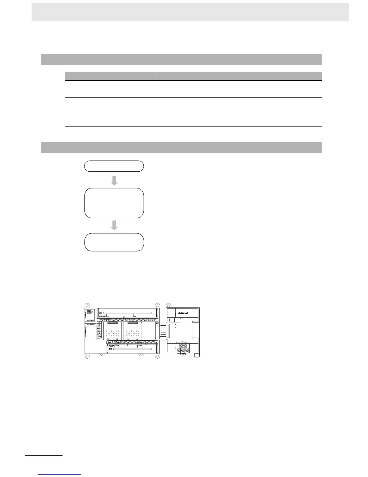
1
Connect the CompoBus/S I/O Link Unit to the CPU Unit.
Connect the Unit.
Determine the node
address of the
CompoBus/S I/O Link Unit
and set the DIP switch.
Wire the CompoBus/S
transmission path.
BD L NC( BS-) N C
BD H NC( BS+
)
S
COMM
ERR
ON
12 3
4
5
6
No
.
SRT21
EXP
CompoBus/S I/O Link Unit
CP1E CPU
Unit
CP1W-SRT21

 Loading...


