5-21
5 Installation and Wiring
CP1E CPU Unit Hardware User’s Manual(W479)
5-3 Wiring
5
5-3-3 I/O Wiring
z Programming Example
In this example, the sensor’s power supply voltage is used as the input to CIO 0.00.
A 100-ms timer delay (the time required for an OMRON Proximity Sensor to stabilize) is created in
the program.
After the Completion Flag for the timer turns ON, the sensor input on input bit CIO 0.01 will cause
output bit CIO 100.00 to turn ON.
z Protective Circuit for Load Short-circuits
If a load connected to the output terminals is short-circuited, output components and the printed cir-
cuit boards may be damaged. To guard against this, incorporate a fuse in the external circuit. Use a
fuse with a capacity of about twice the rated output.
z Connecting to a TTL Circuit
A TTL circuit cannot be connected directly to a transistor output because of the transistor’s residual
voltage. Connect a TTL Unit through a CMOS-IC. It is necessary to connect a pull-up resistor for a
transistor output.
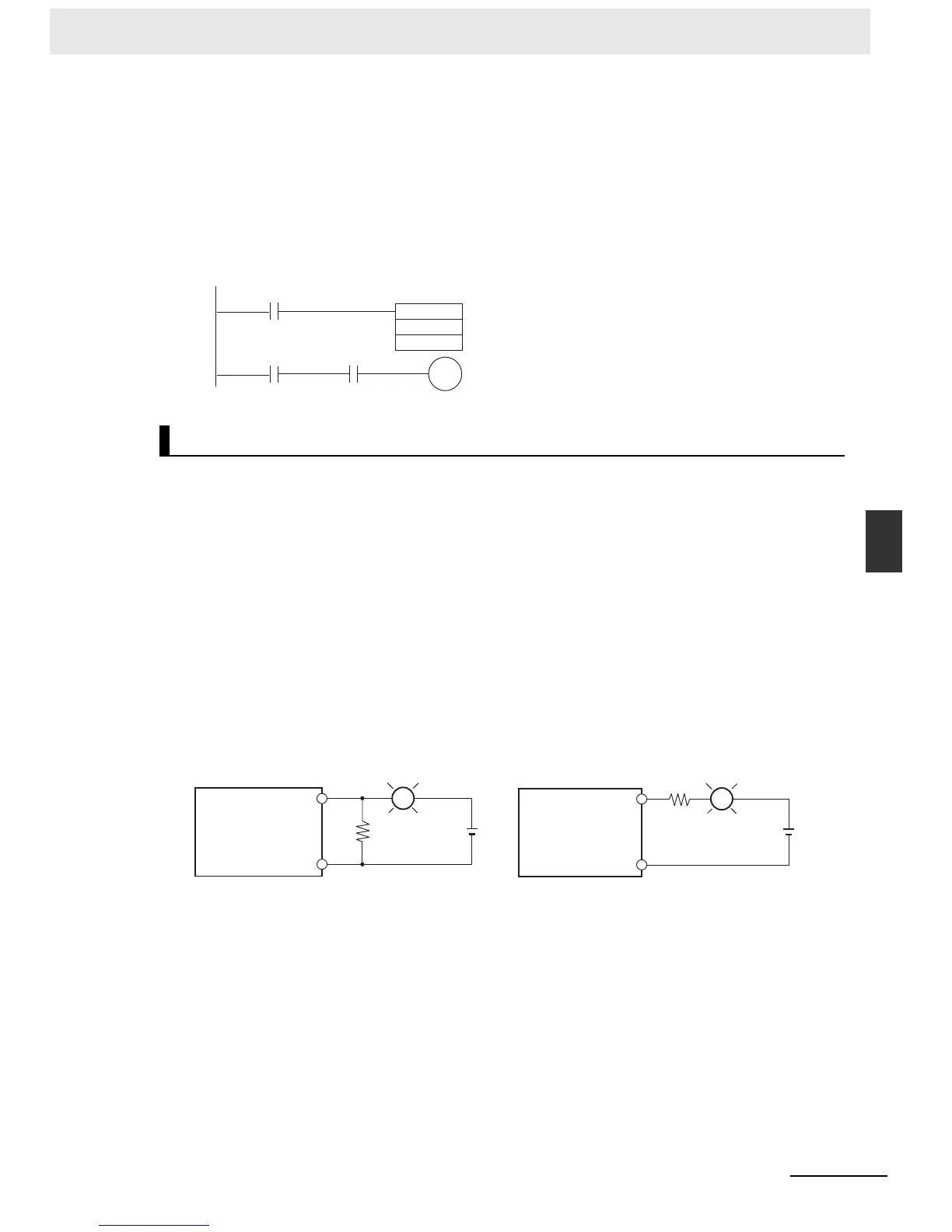
z Precautions on Inrush Current
When connecting a transistor or triac output to a load having a high inrush current (such as an
incandescent lamp), steps must be taken to avoid damage to the transistor or triac. Use either of the
following methods to reduce the inrush current.
Output Wiring
TIM
100
#0001
0.00
100.00
0.01 T100
OUT
R
COM
L
+
[Method1]
SYSMAC CP1E
Providing a dark current of approx. one-third of the
rated value through an incandescent lamp
OUT
R
COM
L
+
[Method2]
Installing a limiting resistor
SYSMAC CP1E

 Loading...


