5-9
5 Installation and Wiring
CP1E CPU Unit Hardware User’s Manual(W479)
5-2 Installation
5
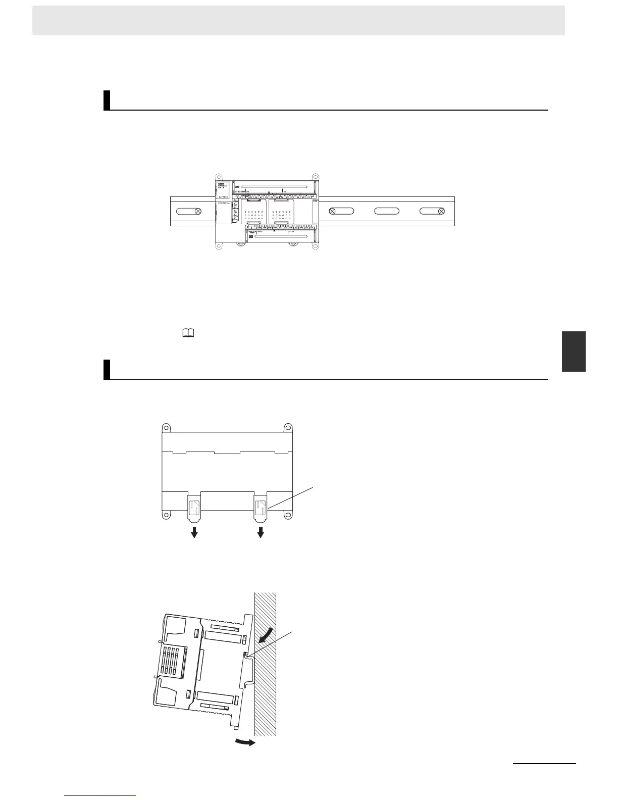
5-2-3 Installation
z DIN Track Installation
Secure the DIN Track with screws in at least three places.
z Surface Installation
A CP1E CPU Unit and CP-series Expansion I/O Units and Expansion Units can be mounted using
M4 screws. For restrictions on the number of Expansion I/O Units and Expansion Units that can be
connected, refer to
2-3 Expansion I/O Unit or Expansion Unit.
1
Use a screwdriver to pull down the DIN Track mounting pins from the back of the Units to
release them, and mount the Units to the DIN Track.
2
Fit the back of the Units onto the DIN Track by catching () the top of the Units on the Track and
then pressing () in at the bottom of the Units, as shown below.
Installation Example
DIN Track Installation
DIN Track
Release
DIN Track mounting pins
DIN Track

 Loading...


