3 Part Names and Functions
3-6
CP1E CPU Unit Hardware User’s Manual(W479)
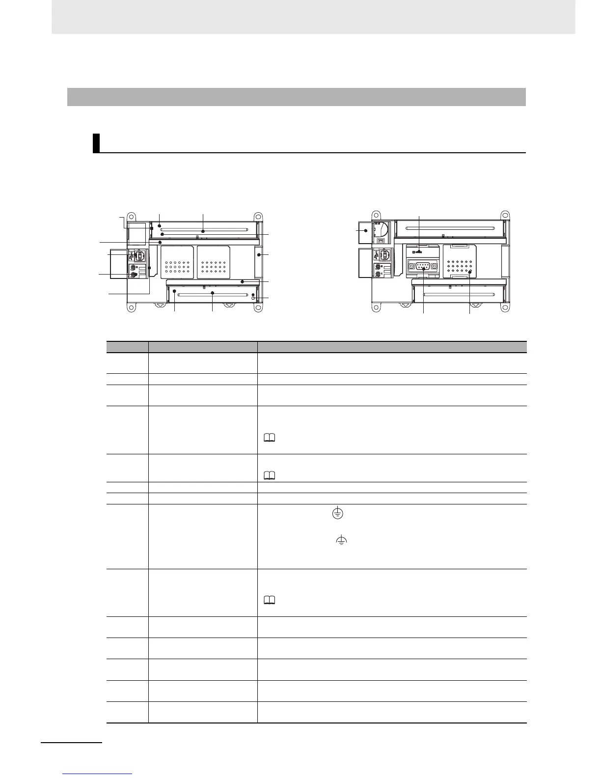
3-1-2 CPU Units with 30 or 40 I/O Points
Part Names and Functions
E-type CPU Unit
CP1E-E30/40DR-A
N-type CPU Unit
CP1E-N30/40D-
Number Name Function
Input terminal block This is the terminal block for inputs such as the power supply input and
24-VDC inputs.
Input indicators (green) Input status is displayed. An indicator will be ON when the input is ON.
Peripheral USB port Used to connect to a personal computer for programming and monitor-
ing by the CX-Programmer for CP1E.
Analog adjusters By turning an analog adjuster, it is possible to adjust the value of A642
or A643 within a range of 0 to 255.
Refer to Section 17 Built-in Functions in the CP1E CPU Unit Soft-
ware User’s Manual (Cat. No. W480).
Operation indicators The CPU Unit’s operating status can be confirmed with this indicator.
Refer to CPU Unit Status Indicators (Page 3-7).
Power supply input terminal Power of 100 to 240 VAC can be supplied.
Input terminals Input devices such as switches and sensors can be connected.
Ground terminal
Protective ground ( ): To prevent electric shock, ground to 100 Ω or
less.
Functional ground ( ): If noise is a significant source of errors or if
electrical shock is a problem, connect to the protective ground terminal
and ground both with a ground of 100Ω or less.
Expansion I/O Unit connec-
tor
CP-series Expansion I/O Units or Expansion Units such as Analogue
I/O Units, and Temperature Sensors can be connected.
Refer to 5-2-4 Connecting Expansion I/O Units and Expansion
Units.
Output indicators (green) Output status is displayed. An indicator will be ON when the output is
ON.
Output terminal block This is the terminal block for outputs such as relay outputs, transistor
outputs, and the external power supply output.
Output terminals Loads such as lamps, contactors, and solenoid valves can be con-
nected.
External power supply ter-
minals
The external supply terminals output up to 300 mA max at 24 VDC.
They can be used as a service power supply for input devices.
Battery cover for N-type
CPU Units
A Battery can be installed by opening the cover. (Battery is optional).
Input terminal
block
Output
terminal
block
Power supply
input terminals
Input terminals
Output terminals
External power
supply
Ground
terminal
Input
indicators
Output
indicators
Peripheral
USB port
Analog
adjusters
Operation
indicators
Expansion
I/O Unit
connector
Battery
cover
Built-in RS-232C communications
status indicator
Serial Option
Board slot
Built-in RS-232C
port

 Loading...


