9 Using Expansion Units and Expansion I/O Units
9-20
CP1E CPU Unit Hardware User’s Manual(W479)
9-3 Analog I/O Units
Each CP1W-MAD11 Analog I/O Unit provides 2 analog inputs and 1 analog output.
• The analog input range can be set to 0 to 5 V, 1 to 5 V, 0 to 10 V, -10 to 10 V, 0 to 20 mA, or 4 to 20
mA. The inputs have a resolution of 1/6000. An open-circuit detection function can be used with the 1
to 5 V and 4 to 20 mA settings.
• The analog output range can be set to 1 to 5 V, 0 to 10 V, -10 to 10 V, 0 to 20 mA, or 4 to 20 mA. The
outputs have a resolution of 1/6000.
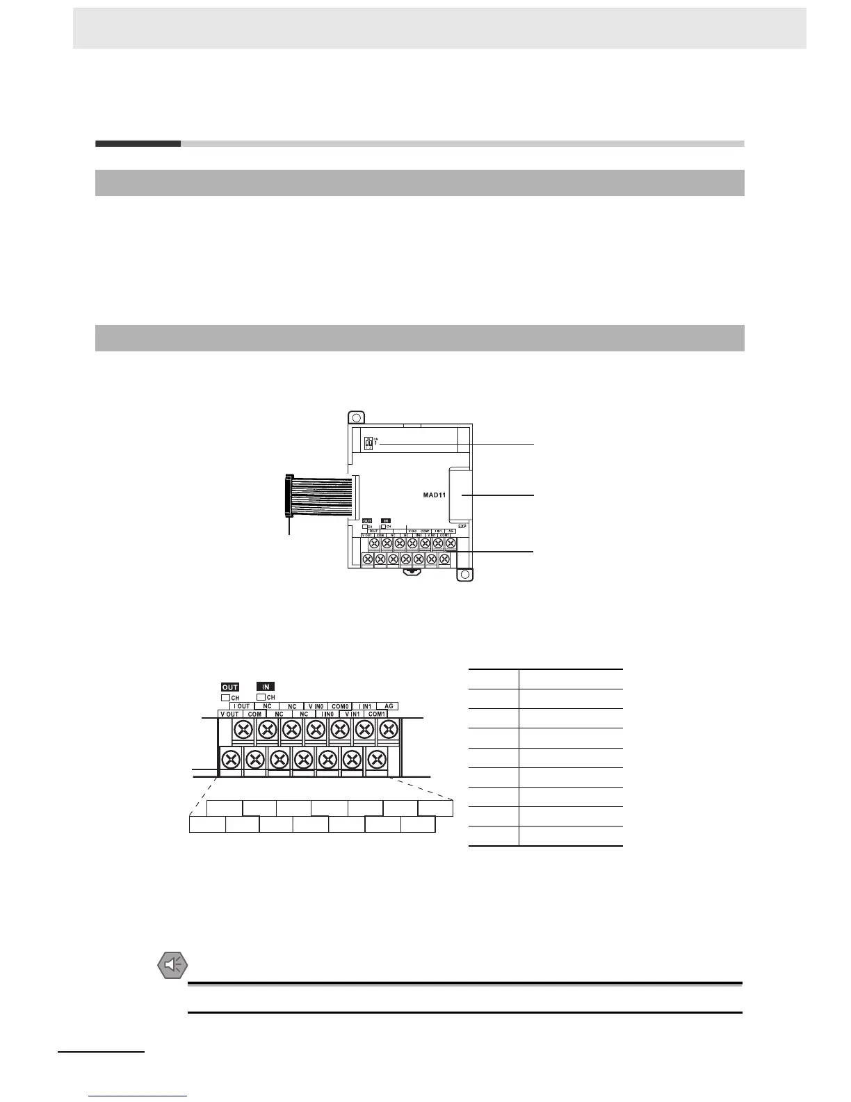
z CP1W-MAD11
(1)Analog I/O Terminals
Connected to analog I/O devices.
• I/O Terminal Arrangements
Note For current inputs, short V IN0 to I IN0 and V IN1 to I IN1.
(2)Expansion I/O Connecting Cable
Connected to the expansion connector of a CPU Unit or an Expansion Unit. The cable is provided
with the Analog I/O Unit and cannot be removed.
Precautions for Safe Use
Do not touch the cables during operation. Static electricity may cause operating errors.
9-3-1 Overview
9-3-2 Part Names and Functions
V OUT Voltage output
I OUT Current output
COM Output common
V IN0 Voltage input 0
I IN0 Current input 0
COM0 Input common 0
V IN1 Voltage input 1
I IN1 Current input 1
COM1 Input common 1
NC
NC
(3) Expansion connector
(2) Expansion I/O connecting cable
(1) Analog I/O terminals
(4) DIP switch
I OUT V IN0 COM0
V OUT
COM I IN0
I IN1
V IN1 COM1
NC NC
AGNC NC

 Loading...


