Appendices
A-28
CP1E CPU Unit Hardware User’s Manual(W479)
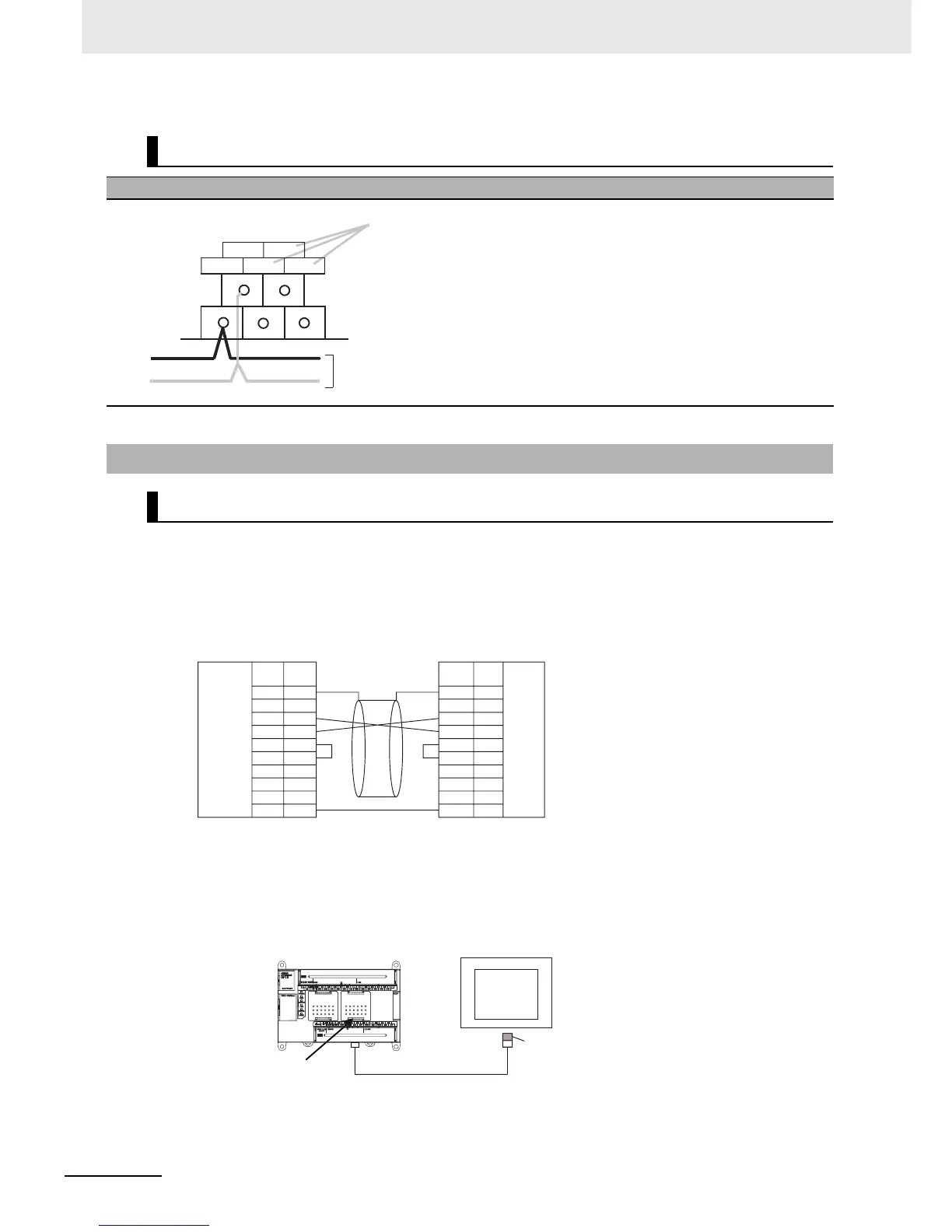
z Connecting a PT and a PLC 1:1 with RS-232C Ports
• Communications Mode: 1:N NT Link, N = 1 only
• OMRON Cables with Connectors: XW2Z-200T (2 m)
XW2Z-500T (5 m)
z Connecting a PT and a PLC with 1:N NT Link and RS-422A/485 Ports Using
4-wire, RS-422A Communications
• Communications mode: 1:N NT Link, N = 1 max.
CP1W-SRT21 CompoBus/S I/O Link Unit
Wiring Diagrams
A-3-4 Serial Communications
Wiring Examples for PTs Using NT Link
BD L
BD H
Connect the CompoBus/S Communications Cable.
BD L
BD H
NC (BS+)
NC
NC (BS−)
These terminals are not used. They can
however be used as communications power
supply relay terminals.
FG
–
SD
RD
RS
CS
5V
–
–
SG
FG
FG
SD
RD
RS
CS
5V
DR
ER
SG
PT
1
2
3
4
5
6
7
8
9
1
2
3
4
5
6
7
8
9
CP1E N-type CPU Unit
Signal SignalPin Pin
Hood Hood
Built-in
RS-232C
Port
D-sub, 9-pin connector (male) D-sub, 9-pin connector (male)
RS-232C
interface
(CP1W-CIF11/12)
CP1E N-type CPU Unit
NS-series PT (Unit No. 0)
RS-422A/485 Option Board
RS-422A Conversion
Unit
(NS-AL002)
1:N NT Link

 Loading...


