A-29
Appendices
CP1E CPU Unit Hardware User’s Manual(W479)
A-3 Wiring Diagrams
App
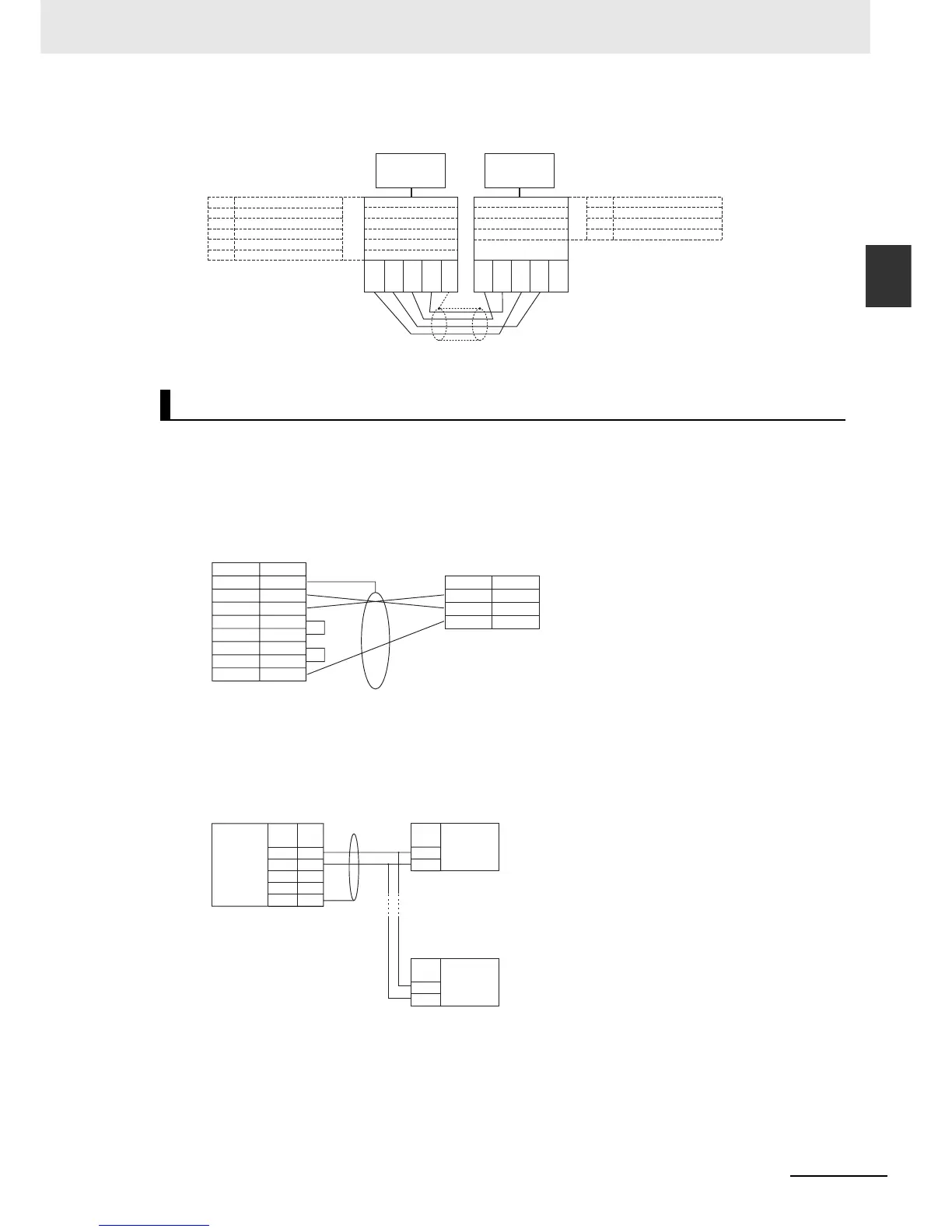
A-3-4 Serial Communications
z Wiring Example
z Connecting RS-232C Ports 1:1
• Communications Mode: No-protocol
Example: Connections to E5CK Controller
z Connecting RS-422A/485 Ports 1:N with 2-wire Connections
• Communications Mode: No-protocol
No-protocol Communications
CP1E
SW1
SW2
SW3
SW4
SW1
SW2
SW3
SW4
SW5
SW6
RDA-
RDB+
SDA-
SDB+
FG
RDA-
RDB+
SDA-
SDB+
FG
RS-422A/485 Option Board
DIP switch for operation settings
Terminating resistance ON/OFF
2/4-wire selection
2/4-wire selection
Not used
RD control
SD control
ON (terminating resistance)
OFF (4-wire connection)
OFF (4-wire connection)
OFF
OFF (no control)
OFF (no control)
NS-series PT
(Unit No. 0)
ON (RS/CS control)
OFF (4-wire connection)
OFF (4-wire connection)
ON (terminating resistance)
RS/CS control or always ON
2/4-wire selection
2/4-wire selection
Terminating resistance ON/OFF
NS-AL002
DIP switch settings
FG
SD
RD
RS
CS
DR
ER
SG
13
14
1
SD
RD
SG
1
2
3
4
5
7
8
9
CP1E N-type CPU Unit
Built-in RS-232C Port or RS-
232C Option Board
Signal
Signal
Pin
RS-232C
shielded cable
D-sub, 9-pin connector (male)
Example: OMRON E5CK Controller
RS-232C: Terminal block
Terminal
3
4
1
2
5
SDA-
SDB+
RDA-
RDB+
FG
A(-)
B(+)
CP1E N-type CPU Unit
RS-422A/485
Option Board
Signal
Signal
Pin
Terminal block
Device supporting
RS-422A/485
communications (2-wire)
Device supporting RS-422A/485
communications (2-wire)
RS-422A/485
interface
A(-)
B(+)
Signal
RS-422A/485
interface

 Loading...


