Appendices
A-30
CP1E CPU Unit Hardware User’s Manual(W479)
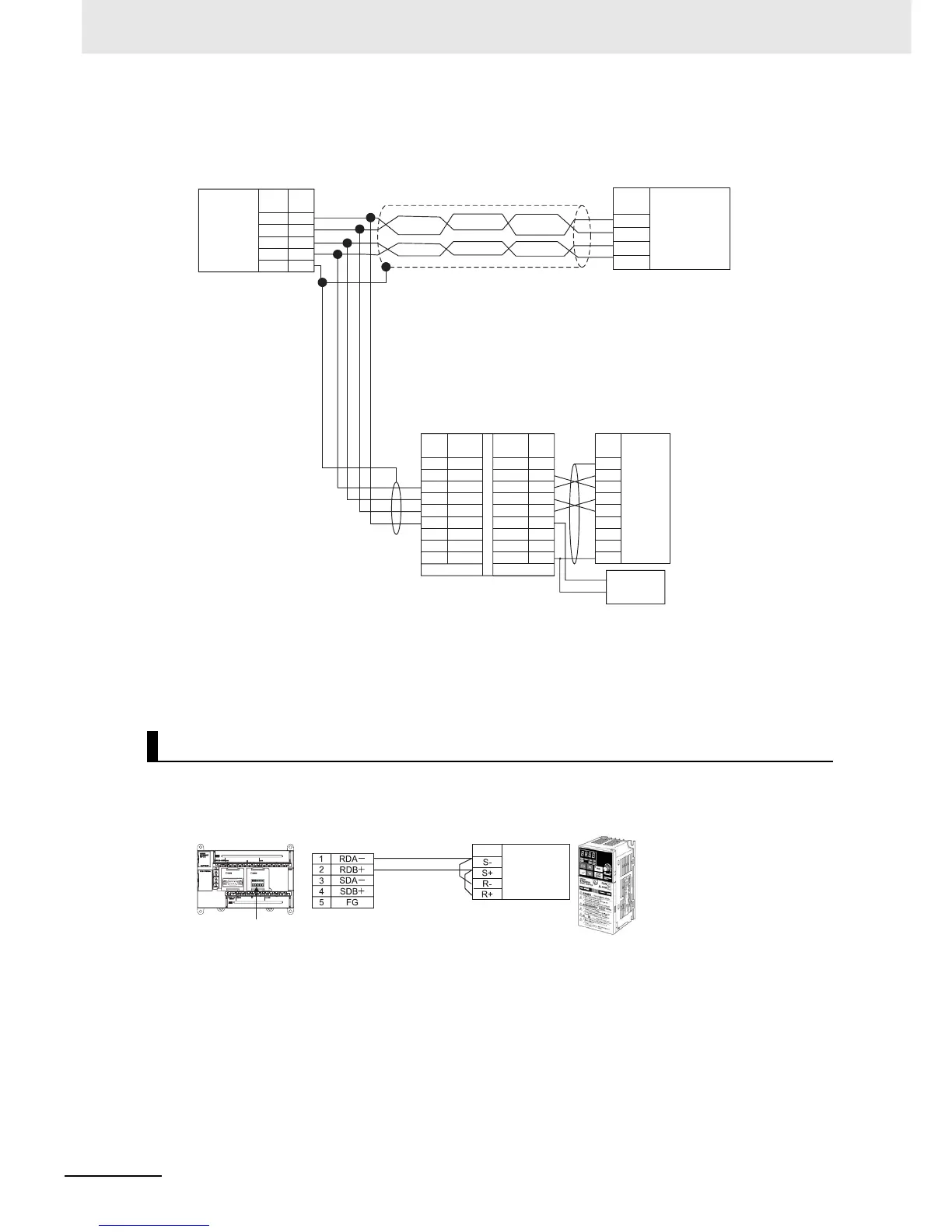
z Connecting RS-422A/485 Ports 1:N with 4-wire Connections
• Communications Mode: No-protocol
• Communications mode: Modbus-RTU Easy Master
Modbus-RTU Easy Master Function
3
4
1
2
5
SDA-
SDB+
RDA-
RDB+
FG
RS-232C
FG
SD
RD
RS
CS
DR
ER
SG
1
2
3
4
5
6
7
8
GRD
SG
SDB
SDA
RDB
RDA
CSB
CSA
1
2
3
4
5
6
7
8
9
RS-232RS-422
NC
SD
RD
RS
CS
5V
DR
ER
SG
DIP SW
SW1-1: ON
SW1-2: ON(Terminating resistance)
SW1-3: OFF
SW1-4: OFF
SW1-5: OFF
SW1-6: ON
RDA
RDB
SDA
SDB
NT-AL001
(+)5V
(−)Power
CP1E N-type CPU Unit
RS-422A/485
Option Board
Signal Pin
Terminal block
Terminal block
4-wire
Terminating
resistance:
ON
Signal
Device supporting RS-422A/485
communications
RS-422A/485
interface
Signal SignalSignalPin Pin
Shield
Shield
D-sub, 9-pin
connector (male)
Device supporting
RS-422A/485
communications
RS-232C
interface
CP1W-CIF11/12
2-wire
CP1W-CIF11/12
CP1E N-type
CPU Unit
Signal
RS-422A/485 Option Board
Control circuit
terminal block
(communications
terminals)
50m max.
RS485
3G3MV

 Loading...


