3 Part Names and Functions
3-14
CP1E CPU Unit Hardware User’s Manual(W479)
CP1E-N30/40DT(1)-A, CP1E- N20DT(1)-A
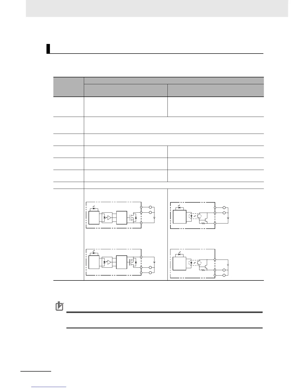
z Normal Outputs
*1 Also do not exceed 0.9 A for the total for CIO 100.00 to CIO 100.03.
*2 The bits that can be used depend on the model of CPU Unit.
Precautions for Correct UsePrecautions for Correct Use
Do not connect a load to an output terminal or apply a voltage in excess of the maximum switch-
ing capacity.
Output Specifications for Transistor Outputs (Sinking or Sourcing)
Item
Specification
CIO 100.00 and CIO 100.01*
1
CIO 100.02 to CIO 100.07 and
CIO 101.00 to CIO 101.07*
2
Maximum
switching
capacity
0.3 mA/output, 0.9 A/common
4.5 to 30 VDC
CP1E-N20D-: 1.8 A Unit
CP1E-N30D-: 2.7 A Unit
CP1E-N40D-: 3.6 A Unit
Minimum
switching
capacity
1 mA 4.5 to 30 VDC
Leakage
current
0.1mA max.
Residual
voltage
0.6 V max. 1.5V max.
ON response
time
0.1 ms max. 1 ms max.
OFF response
time
0.1 ms max. 1 ms max.
Fuse Not provided.
Circuit
configuration
• Normal outputs: CIO 100.00 to CIO
100.01 (sinking)
• Normal outputs: CIO 100.00 to CIO
100.01 (sourcing)
• Normal outputs: CIO 100.02 to CIO 101.07
(sinking)
• Normal outputs: CIO 100.02 to CIO 100.07, CIO
101.00 to CIO 101.07 (sourcing)
OUT
OUT
~
COM(–)
L
L
Internal
circuits
Internal
circuits
24 VDC,
4.5 to 30
VDC
Internal
circuits
OUT
OUT
L
L
COM(+)
Internal
circuits
24 VDC,
4.5 to 30
VDC
~
OUT
OUT
COM(–)
L
L
24 VDC,
4.5 to 30
VDC
Internal
circuits
~
OUT
OUT
COM(+)
L
L
24 VDC,
4.5 to 30
VDC
Internal
circuits
~

 Loading...


