6-3
6 Troubleshooting
CP1E CPU Unit Hardware User’s Manual(W479)
6-1 Troubleshooting CPU Unit Errors
6
6-1-3 Checking Detailed Status
Use the following procedure to read the error status.
You can check detailed error status using information registered in the Auxiliary Area.
The following error details are registered.
If the error status could not be checked when the error occurred, it can be checked by reading error log
data.
The following information is stored in the error log.
• Error code (This is the same error code as is stored in word A400.)
• Error contents
• Time of occurrence
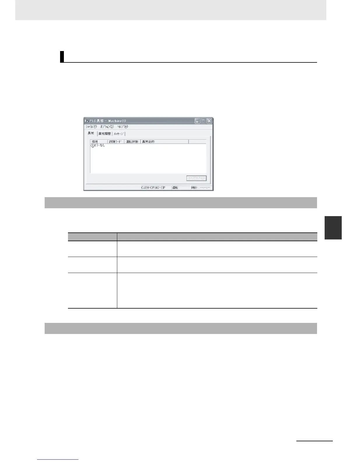
Checking Error Status with the CX-Programmer
1
Place the CX-Programmer online with the CPU Unit.
2
Double-click Error Log in the project tree in the main window.
The PLC Error Window will be displayed. Click the Errors Tab. The current errors will be dis-
played on the Errors Tab Page.
6-1-3 Checking Detailed Status
Area Description
Error flags The Auxiliary Area contains flags that indicate the type of error.
Error information is provided for various types of error.
Error information The Auxiliary Area contains words that provide detailed information on current errors.
Error information is provided for various types of error.
Error code The Auxiliary Area contain a word that provides a code that describes the error that has
occurred.
The error code is stored in A400 for all errors.
If two or more errors occur at the same time, the highest (most serious) error code will be
stored in A400.
6-1-4 Reading Error Log Information

 Loading...


