A-31
Appendices
CP1E CPU Unit Hardware User’s Manual(W479)
A-3 Wiring Diagrams
App
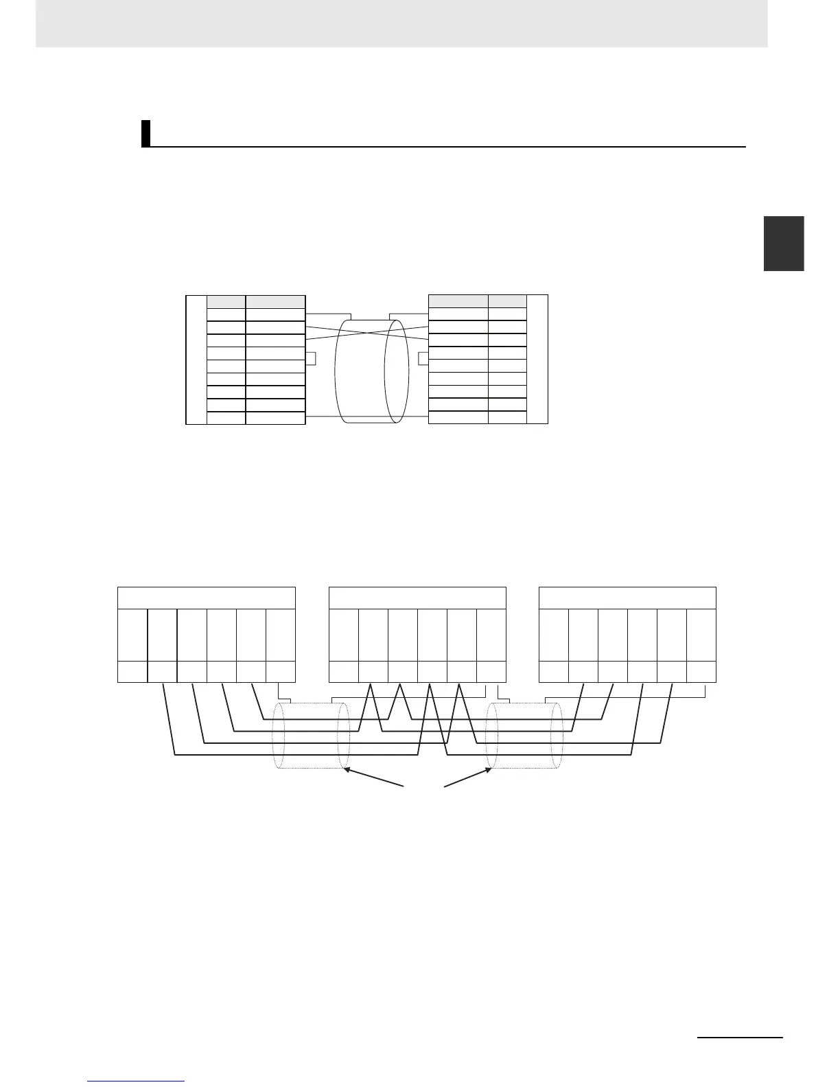
A-3-4 Serial Communications
• Communications mode: Serial PLC Link (Master) or Serial PLC Link (Slave)
z Connection with RS-232C Ports
RS-232C connection is also possible when using a Serial PLC Link to connect two CP1E N-type
CPU Units.
• Wiring Example Using RS-422A/485 Ports with RS-422A, 4-wire Connections
Serial PLC Links
Signal Pin
SignalPin
1
2
3
4
5
6
7
8
9
1
2
3
4
5
6
7
8
9
FG
SD
RD
RS
CS
5V
DR
ER
SG
FG
SD
RD
RS
CS
5V
DR
ER
SG
R
S
2
3
2
C
-
R
S
2
3
2
C
-
CP1E N-type CPU Unit
Built-in RS-232C Port or RS-232C
Option Board
CP1E N-type CPU Unit
Built-in RS-232C Port or RS-232C
Option Board
1 2 3 4 5
DIP SW
SW1:
SW2:
SW3:
SW4:
SW5:
SW6:
SW1:
SW2:
SW3:
SW4:
SW5:
SW6:
SW1:
SW2:
SW3:
SW4:
SW5:
SW6:
DIP SW DIP SW
RDA–
RDB
+
SDA–
SDB
+
FG
RDA–
RDB
+
SDA–
SDB
+
FG
RDA–
RDB
+
SDA–
SDB
+
FG
1 2 3 4 5 1 2 3 4 5
CP1E N-type CPU Unit
Built-in RS-232C port
CJ1W-CIF11 RS-422A Conversion Unit
ON (with terminating resistance)
OFF (4-wire connection)
OFF (4-wire connection)
OFF
OFF (no RS control for RD)
OFF (no RS control for SD)
RS-422A/485 interface RS-422A/485 interface
Signal name
Pin
Signal name
Pin
RS-422A/485 interface
Signal name
Pin
CP1E N-type CPU Unit (Polled Unit No. 0)
CP1W-CIF11 RS-422A/485 Option Board
OFF (no terminating resistance)
OFF (4-wire connection)
OFF (4-wire connection)
OFF
OFF (no RS control for RD)
ON (with RS control for SD)
CJ1M CPU Unit (Polled Unit No. 1)
CJ1W-CIF11 RS-422A Conversion Unit
ON (with terminating resistance)
OFF (4-wire connection)
OFF (4-wire connection)
OFF
OFF (no RS control for RD)
ON (with RS control for SD)
Shield

 Loading...


