2-3
2 Basic System Configuration and Devices
CP1E CPU Unit Hardware User’s Manual(W479)
2-1 Basic System Configuration
2
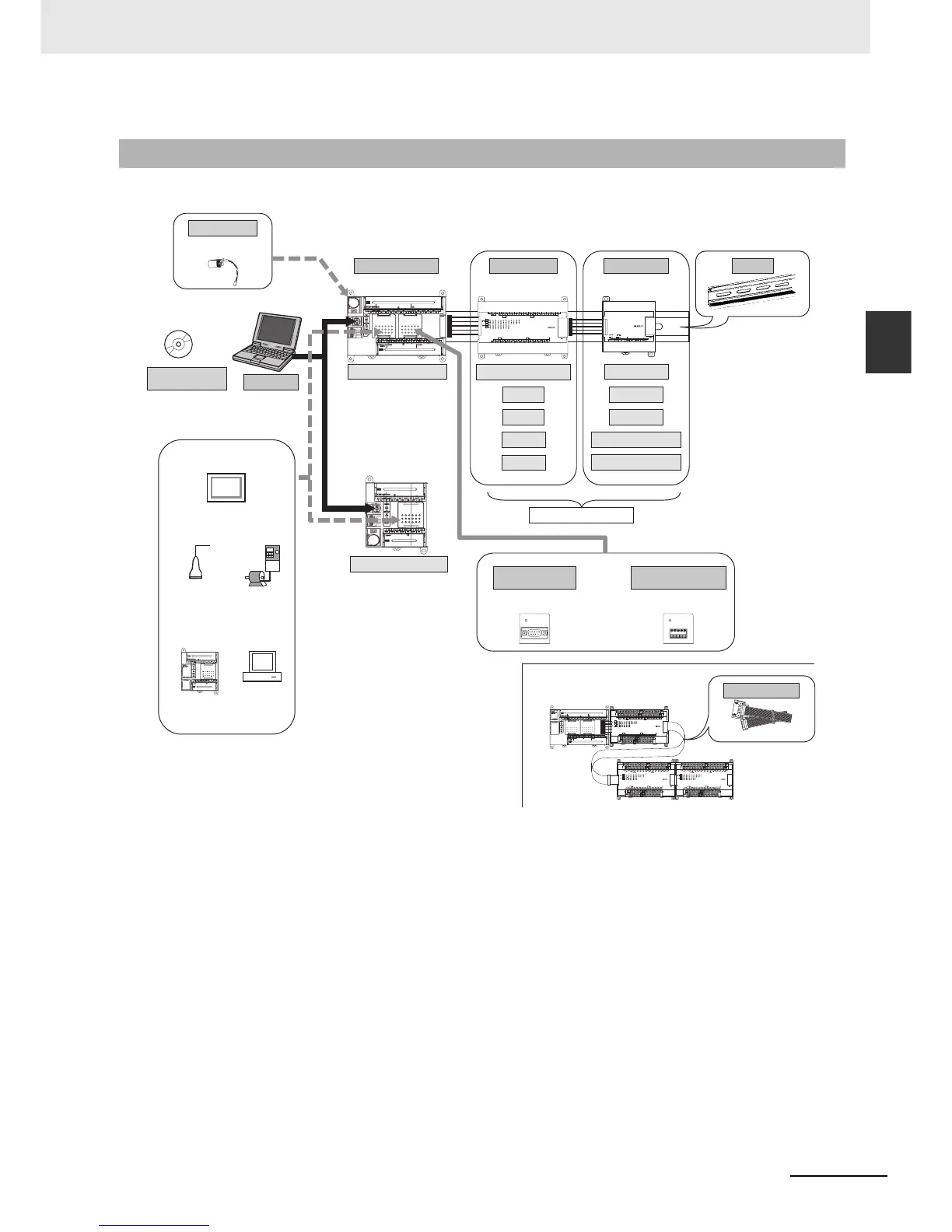
2-1-2 Basic System Configuration Using an N-type CPU Unit
The system configuration when using a CP1E N-type CPU Unit is shown below.
2-1-2 Basic System Configuration Using an N-type CPU Unit
COMM
COMM
CP1E-N30-A
CP1E-N40-A
CP1E-N20-A
CPU Unit with 30 or 40 I/O Point
CPU Unit with 20 I/O Points
CP1E CPU Unit
Expansion I/O Units Expansion Units
CPU Unit with 20 or 40 I/O Points
8 inputs
8 outputs
16 outputs
32 outputs
Analog I/O
Analog inputs
Analog outputs
Temperature sensors
CompoBus/S I/O Link Unit
Up to 3 Units can be connected
DIN Track
CP1W-CN811
CP1E CPU Unit
Expansion Units and
Expansion I/O Units
I/O Connecting Cable
Personal computer
Support Software
CX-Programmer for CP1E
IBM PC/AT or equivalent
RS-232C Option Board
CP1W-CIF01
RS-422A/485 Option Board
CP1W-CIF11
CP1W-CIF12
Or
Battery
CP1W-BAT01
When a two level layout is created by expansion and distance is required
(NT Link)
General component
(No-protocol mode)
(Modbus-RTU)
CP-series PLC or
CJ1M PLC
(Serial PLC Link)
Host computer
(Host Link)
Programmable
Terminal (PT)
*Neither the CP1W-DAM01 LCD Option Board nor the CP1W-CIF41
Ethernet Option Board can be used.
Inverter

 Loading...


