2 Basic System Configuration and Devices
2-2
CP1E CPU Unit Hardware User’s Manual(W479)
2-1 Basic System Configuration
This section describes the system configurations using E-type and N-type CP1E CPU Units.
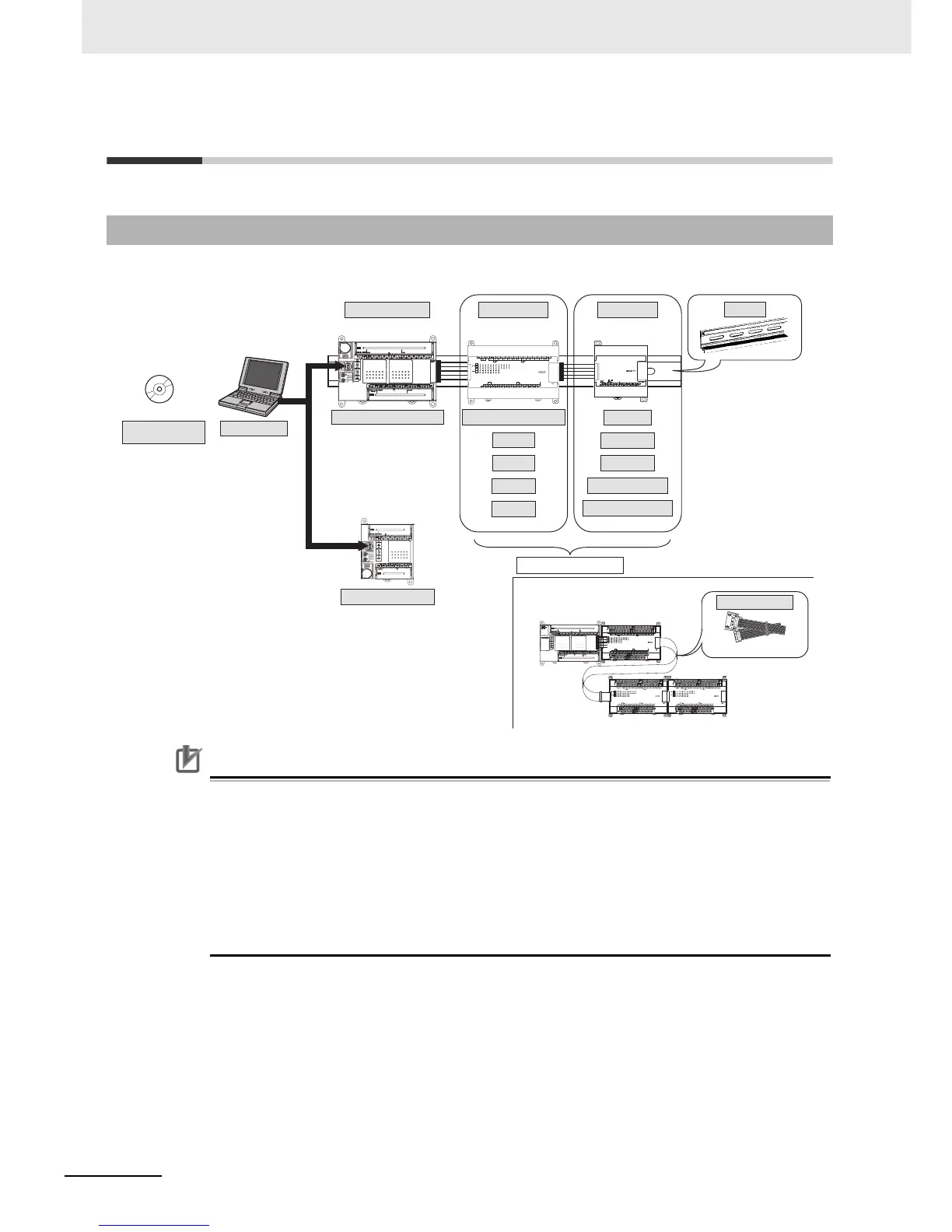
The system configuration when using a CP1E E-type CPU Unit is shown below.
Precautions for Correct UsePrecautions for Correct Use
For CP1E CPU Units, the following I/O memory area will be unstable after a power interruption.
• DM Area (D) (excluding words backed up to the EEPROM using the DM function)
• Holding Area (H)
• Counter Present Values and Completion Flags (C)
• Auxiliary Area related to clock functions(A)
Mount the CP1W-BAT01 Battery (sold separately) to an N-type CPU Unit if data in the
above areas need to be retained after a power interruption. A Battery cannot be mounted to
an E-type CPU Unit.
2-1-1 Basic System Configuration Using an E-type CPU Unit
Personal computer
CP1E-E30-A
CP1E-E40-A
CP1E-E20-A
Support Software
CX-Programmer for CP1E
CPU Unit with 30 or 40 I/O Points
IBM PC/AT or equivalent
CPU Unit with 20 I/O Points
CP1E CPU Unit Expansion I/O Units Expansion Units
CPU Unit with 20 or 40 I/O Points
8 inputs
8 outputs
16 outputs
32 outputs
Up to 3 Units can be connected
CP1W-CN811
CP1E CPU Unit
Expansion Units and
Expansion I/O Units
I/O Connecting Cable
When a two level layout is created by expansion and distance is required
DIN Track
Analog I/O
Analog inputs
Analog outputs
Temperature sensors
CompoBus/S I/O Link Unit

 Loading...


